Functional restoration of locomotive for use by ARM.
Manufacturer: Baldwin Locomotive Works, Eddystone, PA (Philadelphia)
Model: DRS-6-6-1500 (Diesel Road Switcher, 6-axles, 6-traction motors, 1500-horsepower)
Built: July 1950, Order Number: 50507
Serial Number: 74812 (one of 82 units built between 1948 – 1950)
Orignial Owner: McCloud River Railroad, McCloud, CA, locomotive #29.
Sold to Magma Arizona Railroad as locomotive #10.
Diesel Engine: Baldwin Model 608SC, 8 – Cylinder In-Line, 12-3/4” Bore, 15-1/2”-Stroke, 15,832 Cubic In. Displacement, 13.45:1 Compression Ratio, Turbocharged.
Max. Horsepower: 1625 (1500 available for traction)
Max. RPM: 625
Lubricating Oil: 200 gallons
Coolant: 300 gallons
Fuel Capacity: 900 gallons
Generators: Main: Westinghouse 471B, Auxiliary: Westinghouse YG42B
Traction Motors: Westinghouse (6 each)
Trucks: C-C, General Steel Castings, “Commonwealth” Cast Frames
Truck Wheel Base: 13’-00” (note unequal axle spacing)
Truck Centers: 32’-03”
Wheel Diameter @Tread: 42”
General Info
Equipped with Multiple-Unit Controls
Equipped with Dynamic Brakes
Coupled Length: 58’-00”
Height from Rail to Top of Cab: 14’-00”
Weight, Working Order: 292,000 lbs (reduced weight model; 325,000 lbs was standard)
Maximum Safe Speed: 60 MPH
|
|
|
|
||
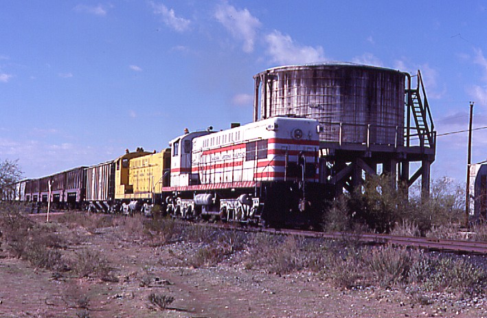
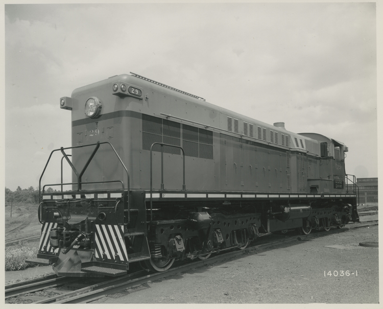
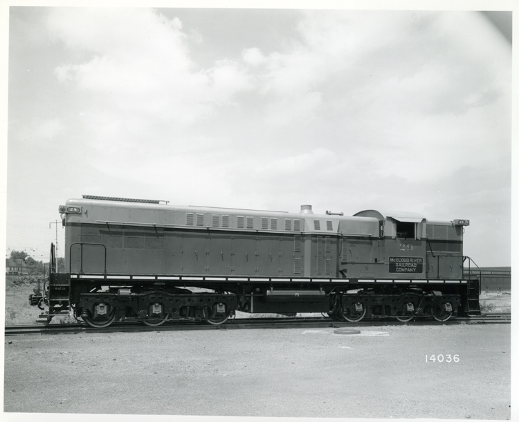
| Magma Arizona #10, at Desert Wells Tank, 1/15/80. Photo by: Bob Trennert | Baldwin Builder Photo taken in 1950 at Eddystone, PA as McCloud #29. Source: Baldwin-Hamilton Collection, Courtesy of Pennsylvania Historical and Museum Commission, Pennsylvania State Archives | Baldwin Builder Photo taken in 1950 at Eddystone, PA as McCloud #29. Source: Baldwin-Hamilton Collection, Courtesy of Pennsylvania Historical and Museum Commission, Pennsylvania State Archives |
Lionel Trains, in anticipation of introducing a sound-equipped model of a Baldwin DR-12-8-1500/2 ‘Centipede’ locomotive, needed an accurate recording of a model 608SC diesel engine. Our Baldwin DRS-6-6-1500 locomotive contains one of the very few operating examples of this engine, so Lionel made arrangements with the museum to record the sounds of our locomotive: engine starting, various RPM settings, horn, bell, brake releases, and engine shut down. This recording is a small sample of several hours-worth of high-quality digital recordings made on Dec 03, 2011. It is used here by permission of Lionel LLC, copyright 2012.
Although the recording contains some loud sounds, it’s
recommended to turn up the volume to best capture all the nuances of the
engine’s character. The first sound heard is the engine slowly turning over.
There is no separate starting motor noise since the engine is being turned by a
special winding on the main generator, energized by the batteries. As the engine
gains speed, and just before it roars to life, the doors of the engine
compartment can be heard rattling. Once the engine starts, the RPM varies up and
down for a moment until the governor settles down to a steady idle. Listening
carefully, the sound of the turbocharger coming up to speed can be heard at
about 20-30 seconds into the recording.
After the engine idles for a moment, a blast of the horn is heard. Since the
locomotive’s two horns are of different styles, a distinct two-tone note is
heard. If you’re listening in stereo, you can discern the position of the front
and rear horns.
At last the engine is shut down, and just before it stops, the engine
compartment doors can again be heard rattling. A final rushing-air sound is the
turbocharger winding down after the engine has stopped.
X Click here to listen
August 2013
Removed the covers on the two air cylinders for the reverser, and found much
dirt and little lubrication. Cleaned the cylinders and lubricated the packing
with neat’s foot oil. Tested the reverser using shop air, and despite the lower
than normal pressure, the reverser seemed to work much better than usual.
Created a small wooden frame and cover for the horn valve access hole in the cab
ceiling.
June - July 2013
Installed the remaining trim strips on the cab ceiling, set a few protruding
staples, and used Durham’s Water Putty to fill the resulting holes. Sanded the
water putty smooth.
Retrieved two barrels of lube oil from the bullpen, but discovered that both
barrels were contaminated with water. Only about 28 quarts were successfully
siphoned off the top and added to the crankcase. The dip stick now reads above
the ‘low’ mark, but it’s still along way to the ‘full’ mark.
May 2013
Performed the usual tasks in preparation for National Train Day: moved the loco
north and set-up the entry/exit steps; vacuumed and washed the cab interior and
exterior areas where visitors might touch; put up signage; and set up the long
air hose.
NTD went well, with many visitors enjoying the horn blowing, even if some of
them required a little coaxing of their inner child before they would pull the
chain. Only the north-facing horn was operating, which really helped with the
noise-annoyance factor south of the locomotive. Even though it was a hot day, a
nice cross-breeze and the newly insulated ceiling made the cab quite comfortable
even into the afternoon.
After NTD, the locomotive was moved back to its usual position so that the
battery charger could be reconnected.
April 2013
Purchased two 4’x8’ sheets of ¾” thick, foil-backed foam insulation, and three
4’x8’ sheets of 1/8” thick tempered hardboard for the cab ceiling project.
Loctite’s ‘Heavy Duty Powergrab’ worked very well to secure the foam, with no
clamping or bracing required for the foam to follow the curve of the steel
ceiling. A significant reduction in radiated heat off the steel roof was
immediately noted, even before installation of the foam was complete. The
hardboard ceiling was divided into six panels, instead of the original three.
This made it possible to fit the new panels behind the existing wall panels.
Each panel was tacked into place with a pneumatic stapler, and then permanently
secured with countersunk screws. After a light sanding to level out the seams,
narrow strips of hardboard were stapled and glued over the seams to hide them.
The original hardboard bezel around the ceiling light was cleaned up, and
secured in place. The bulb socket was cleaned up, and the bulb cage was stripped
and re-painted.
The ceiling project is not complete, but its appearance is much improved for
National Train Day.
March 2013
The locomotive was successfully operated on March 16. All went well, and even
the reverser gave little trouble, probably due to the warmer weather. Lube oil
is now very low and must be replenished before the next operating session.
February 2013
The locomotive was started successfully on Feb-02, with the usual problems with
reverser and air compressor controller. No further problems were observed with
the AUX GEN switch. The lube oil is not at the ‘low’ mark yet, but it’s getting
close, so it will need replenishing soon. The crew practiced using hand signals,
coupling and uncoupling, handling air hoses and angle cocks, handbrakes, wheel
chocks and skates, and using the automatic air brakes.
After the operating session, the battery charger input cable shorted while being
handled. This was due to crumbling insulation on the very old wire. Potential
replacement cable on-hand was judged to be in a similar unusable condition. A
bit of luck secured the donation of an ample quantity of nearly new 6-AWG,
4-conductor welding cable. The new cable has been installed and the charger is
back on-line.
January 2013
Purchased a 2x4 foot sample of 1” EPS foam board with foil backing. Made a test
installation in the cab ceiling, and determined that the material is flexible
enough to follow the curve of the roof. This will be used to insulate the cab
ceiling, an upgrade to the original design (which was no insulation).
October 27, 2012
The locomotive was started and operated successfully, performing minor switching
in the yard. The reverser and the air compressor controller gave their usual
troubles, but they did not interfere with operations. Upon shut down, it was
discovered that the AUX GEN circuit breaker would not stay in the OFF position.
A little jiggling got it working again but this will be investigated further
before the next operating session. We may have a spare breaker in an unused
circuit. Alan Rybarchyk cleaned the placards and replaced the US and Arizona
flags.
October 20, 2012
Another 45 gallons of fuel was added, which brought the level up to where it
shows on the gauge.
October 06, 2012
The locomotive was started after a hiatus of nearly six months. Cranking was
robust (indicating healthy batteries) and the engine started easily. The
locomotive ran very smoothly, with no problems experienced, other than a little
initial trouble with the reverser. The exhaust was very clean, and even the
diesel-dots seemed fewer and smaller than normal.
September 29, 2012
45 gallons of diesel fuel was added, and the battery water was replenished. The
remaining pieces of the cab ceiling were removed and the cab vacuumed. The wires
for the old roof beacons (now long gone) were removed from the ceiling. The
ceiling is now ready to receive new panels.
July 2012
The underlying wood framework for the cab’s ceiling was repaired and re-secured
to the steel roof. Much of the original hardware was loose or missing.
With some of the ceiling panels removed, the air pipe for the rear-facing horn
was exposed, allowing the installation of another shut-off valve. A small access
panel will allow the valve to be operated once the ceiling is replaced. Now,
either horn may be shut-off as needed, which means that for next NTD, only the
north-facing horn will be used.
June 2012
Work has started on removing the interior ceiling panels in the cab. The old
material, similar to 1/8” Masonite, is cracked and missing several large pieces.
A hole in the cab roof was patched. A shut-off valve was installed on the roof
for controlling the front-facing horn.
May 12, 2012
National Train Day! The locomotive was a popular attraction with the opportunity
to blow the horn. Which they did…all day long. The rear horn was turned off, but
with the front horn facing the display yard, it was very loud. Plan for next
year: operate only the rear, north-facing horn!
April 14, 2012
The locomotive was successfully started and operated. The reverser caused its
usual problems. In preparation for National Train Day, the locomotive was parked
at the north end of the yard and the steps were put into place. The gangplanks
were modified to match the level between the steps and the locomotive walkway.
An existing pulley/belt shroud was adapted and mounted to a stationary air
compressor that will be used to supply air for NTD horn blowing
Alan Rybarchyk created another permanent placard for the locomotive. This one
will list the technical specifications for the locomotive.
The locomotive
started easily and ran well for about 90-minutes. The reverser would not operate
on its own for the entire session, indicating its worsening condition.
Alan Rybarchyk and Kyle Sikes took new temperatures readings of each cylinder’s
exhaust manifold, using a non-contact infrared thermometer. Before adjusting the
fuel rack settings, the range of cylinder temperatures was 129 degrees. The new
readings show that the range has been reduced to 45 degrees. Although this is
still far from the recommended variation of only 15 degrees between cylinders,
it shows that our adjustments are going in the right direction.
We received the sample sound recording made by Lionel, and Steve Whisel is
working on adding it to our website.
Thanks to Alan Rybarchyk, we received two builder’s photos of McCloud River RR
#29, as #10 was known when new. These came from the Baldwin-Hamilton Collection,
Courtesy of Pennsylvania Historical and Museum Commission, Pennsylvania State
Archives. Digital copies are on the way that will allow posting on our website.
Alan Rybarchyk mounted United Sates and Arizona flags on the locomotive.
January 21, 2012
The locomotive was started and operated. Cranking was vigorous, which indicates
that our new charging schedule is working well. The charger is being run in
‘float mode’ at all times, and switched over to ‘full charge mode’ one week
before a planned start. Only a minimal amount of battery water is being consumed
by this charging schedule. Added about three gallons after checking specific
gravity.
The reverser gave a little trouble until things warmed up, but otherwise the
locomotive ran well for about two hours, during which switching was performed to
move the E8 locomotive onto Track 1. Larry Benedict, Andy Chinn, Alan Rybarchyk,
and Kyle Sikes all had turns at the throttle. It was also the first time that we
employed the newly-repaired bell.
January 14, 2012
The electrical cabinet was blown out with compressed air, in the hopes of
solving some of the recent electrical glitches. Severe dust storms really take
their toll on the unsealed equipment.
December 03, 2011
Lionel Trains is working on a new sound-equipped model of a Baldwin ‘Centipede’,
a monster locomotive that contained two of the same 608SC diesel engine that is
in our Baldwin. Wanting authentic sound for their model, they contacted the
museum about recording the sound of our locomotive. Our locomotive has one of
the very few remaining, operating examples of that model diesel engine. After a
bit of negotiation and planning, the date was set for last Saturday.
The recording engineer showed up shortly thereafter, and set-up his equipment
while we did our own preparations. Four microphones were placed: a stereo pair
about 25 feet from the locomotive, another one near the air compressor, and a
fourth next to the turbocharger. Another tiny recorder with built-in microphone
was placed in my breast pocket, so I could make a running commentary.
When the time came to start recording, a whistle was blown to time-stamp the
multiple recorders, and I pressed the big button. Nothing. After several
attempts, much muttering under my breath and stroking of the control panel, we
finally discovered that one of the starting contactors was welded shut. Since
everything electrical is interlocked, that was preventing the starting circuits
from energizing. A quick poke with a screwdriver got it unstuck, and the
locomotive roared to life. The batteries, my biggest concern, turned out not to
be a problem after all.
It did run a little rough at first, perhaps due to some sticky actuators on the
fuel injector pumps. The RPM was ‘hunting’ up and down, and it took a while
before the governor got it calmed down to a steady idle. Once things got
stabilized and warmed up, we began following a ‘script’ supplied by Lionel. We
recorded several sequences of increasing and decreasing RPM, and finally a shut
down. After the sound engineer checked his recordings, we attempted another
start-up, and again nothing happened. It wasn’t the starting contactor that
time, but after turning switches on and off several times, whatever was
malfunctioning cleared itself and the motor started. The RPM settled right down,
so that was considered a ‘good start’. We repeated the same sequences just to
make sure we got good recordings, all the while listening for planes overhead
from the nearby airport. All of the sounds were recorded with the locomotive
stationary, since we didn’t want any extraneous noises of squealing
wheels-on-rails, etc.
As an aside, I think some of the electrical-contactor problems can be blamed on
the horrible ‘haboob’ dust storm we had a few months ago. That dust got into
everything, including the locomotives electrical cabinet. So we’re thinking a
bit of cleaning with compressed air is in order.
Then we moved on to recording with the engine off, and captured the sound of the
horn, bell, brake releases, and dumping the air. We also included some ‘bonus’
tracks of our wig-wag and crossing gate bells, and even got the local going by
on UP’s Chandler Branch.
So, overall the day was a success, but not without a significant amount of
stress and several periods of frustration. I did learn later that some
malfunction occurred with the recorder in my pocket, thereby losing some of my
commentary. So I’ll probably have to help Lionel figure out some of the
sequences. For our trouble (not that we wouldn’t have been starting it anyway),
Lionel will be making a $250 donation to the locomotive fund, and also agreed to
supply us with a short start-run-stop recording to put on the museum’s website
as a ‘hear the locomotive run’ feature.
Alan Rybarchyk had a very nice all-weather metal sign fabricated, showing a
cut-away view of the locomotive. This will be on permanent display next to the
locomotive.
November 26, 2011
Added 125 gallons of diesel fuel (cost $125). Added seven gallons of battery
water. Lube oil checked okay. Placed charger on full-charge-mode in preparation
for next week’s starting.
October 08, 2011
Removed the bell and ringer mechanism, and replaced the ringer with a new one, a
Prime Manufacturing Corp., Model BR106. The new ringer was configured a little
differently, but it fits fine and the clapper hits the bell only slightly lower
than the original clapper. The air inlet was a different size pipe, so a
reducing bushing was used. The added bushing lengthened the pipe, which
necessitated loosening a pipe clamp so the mating pipe could be shifted upwards.
Tested the bell with shop air applied to the locomotive – works great!
October 01, 2011
Checked lube oil and governor oil – both okay. Added some oil to the forward
bearing of the forward traction motor blower. Oiled and exercised the fuel rack
and the reverser.
Had a little trouble starting the engine. On the first two attempts, the engine
did not turn over. On the third try, the engine barely started turning, then
finally picked up speed and started easily. The battery charger was on ‘float’
since the previous Wednesday afternoon and on ‘charge’ since noon on Friday. Had
some trouble with the contactors engaging for power, but that problem worked
itself out after a few moves back-n-forth.
After a short period of operation, a burning odor was noticed in the cab: it
smelled like burning electronics of a vintage newer than the locomotive. The
odor was traced to the radio, and further confirmed by wisps of smoke coming
from the radio. The power supply fuses were removed (which did not blow despite
the failure of the radio). As this radio had stopped transmitting some time ago,
and with the impending obsolescence of analog RR radio communications, no
attempt will be made to repair or replace the radio (which is not original to
the locomotive).
As before, the air compressor controller is not always kicking back on when the
pressure drops below the set level. A sharp rap on the controller gets it
working again. However, this time we experienced an additional problem after
about 30 minutes of operation. The air pressure would no go above 70 PSI,
despite the compressor sounding like it was pumping. This warrants further
investigation.
September 24, 2011
Received two replacement water jumpers and gasket sets from SMS Raillines (at no
charge!). Painted the water jumpers, and installed one of them on engine
cylinder #1 with new gaskets and hardware. Refilled the coolant system and added
2 additional boxes of water treatment, Industrial Specialty Chemicals ISC-7537UP
Checked water level in a few battery cells, but all looked okay, so no water was
added.
August 27, 2011
Bart Barton found an electrical panel with seven (!) of the Westinghouse circuit
breakers that we’ve been trying to find. Replaced the one defective breaker in
the marker light circuit, and will retain the remainder as spares.
Also verified that fireman’s side track light is working, which is controlled by
the switch next to the fireman’s seat.
August 06, 2011
Scrubbed and washed the tops of the batteries with plain water. Added approx 2
gallons of distilled water to the batteries.
Removed the leaking water jumper on #1 cylinder, only to discover it had been
previously patched with a bit of rubber and a hose clamp. Will contact SMS
Railines to seek their advice on repair or replacement of the water jumper.
July 02, 2011
When operating the battery charger, noted that the meters’ LCD displays turn
completely black with the combination of internally generated heat, the high
ambient temperature and sunlight on the cabinet. The displays returned to normal
operation after cooling down.
Discovered a coolant leak coming from a water jumper, which connects the water
jacket in the block to the individual cylinder heads. Of course, it is the least
accessible of the eight jumpers, on the rear-most #1 cylinder, behind the four
exhaust pipes.
June 04, 2011
Started and operated the locomotive and performed some switching in the yard.
Thanks to recent adjustments of the fuel rack, which equalized the fuel flow to
each cylinder, the engine ran smoother than it has in our history. The sound of
the engine no longer has the familiar 8-beat loping character, and the body of
the locomotive no longer sways back-n-forth in sympathy. Further adjustments are
planned for the fuel rack, using a non-contact thermometer to attain exhaust
temperatures within the specified 15-degree difference between cylinders. Before
the adjustments, temperature differences of over 100-degrees between cylinders
were measured.
A few minor problems were observed: the air compressor controller required a
periodic ‘smack’ to turn on; the horn valve is leaking great quantities of air
when actuated (no doubt worn out after NTD!); and a noise was detected,
apparently coming from the rear traction motor blower (this noise may not be
new, but may now be audible thanks to the reduced rattling of the locomotive’s
parts). The locomotive is getting very low on fuel.
May 22, 2011
Added just over three gallons of distilled water to the batteries. Since it had
been a while since water was added, the relatively small amount of water
required confirms that the new battery charger is working well without charging
the batteries at too high a rate.
May 07, 2011
National Train Day! The cab and engine doors were opened for public inspection,
and visitors were welcomed into the cab to blow the horn. Identifying signs were
hung on the engineer’s controls, and a cut-away view of the locomotive was hung
on the outside railing. A donation box was set-up for the locomotive, which
yielded a disappointing $18 in donations. Idea for next year’s donation box
sign: “Suggested Donation $1”.
The two sets of stairs built for public access to the locomotive’s cab were a
huge help, and significantly increased the safety of the public entering and
exiting the cab. Thanks to all who were involved with the stairs’ construction.
May 06, 2011
Completed the degreasing of the exterior of the locomotive. Positioned the
locomotive at the north end of track #2.
Remounted the refurbished and repainted rear facing horn on the short hood. It
sounds wonderful and nicely complements the sound of the other horn (which is
not the same model). A shut-off valve was installed so that only the
front-facing horn would be operational for National Train Day.
April 23, 2011
Continued with degreasing of the exterior of the locomotive. Painted the horn
mounting plate on the short hood, in preparation for remounting the horn.
April 16, 2011
Continued with degreasing of the exterior of the locomotive. Painted the
refurbished horn and its mounting bracket.
April 09, 2011
Began the long process of degreasing the exterior of the locomotive in
preparation for National Train Day.
April 02, 2011
Did some further troubleshooting on the track light, but the bulb-to-socket
adaptor used for continuity testing may not have been making contact, so tests
will be repeated later. Discovered two more track lights, above the handrails on
the ends of the locomotive. One end appears to be complete with socket and
shade, the other end has neither.
Adjusted fuel rack levers for more equal settings between cylinders. The two
cylinders (#3 and #7) with the highest settings were also the two with the
highest temperatures when measured Jan-22. New temperature readings will be
taken to determine if the cylinders are more balanced now, and if more
adjustment is required.
Received the good news from The Horn Doctor that the horn needed no new parts,
and only required a good cleaning. He says it is the nicest Westinghouse E2
Pneuphonic he’s ever heard. Total bill is $59 including return shipping.
March 26, 2011
Installed removable Plexiglas cover over the cab electrical switches, to prevent
visitor tampering.
Stenciled “Emergency Fuel Cut-off” signs on both sides of the locomotive.
Before starting, noticed that not all of the fuel rack actuating levers were
providing the same action on each fuel injector pump. Adjusted set-screws on
three cylinders (#1, #4 and #5) so that the rack levers began actuating the
pumps as soon as the rack began to turn.
Started easily, RPM was high initially, but settled down to normal after a few
minutes. A little smokier than usual, with occasional detonation sounds like one
or more cylinders were firing harder. Both the smoke and uneven running smoothed
out after less than an hour of running.
Reverser gave no problems. Ran for about two hours. Used locomotive to pull
about six freight cars and the steam locomotive back about 3 feet, to expose a
new section of the steamer’s crosshead guides and piston.
Later comparison with cylinder temperature readings (taken on Jan 22) show some
correspondence between the lowest temperatures and the too-low mis-adjusted fuel
rack levers on cylinders #1, #4 and #5. Need to investigate if some of the
actuating arms may be mis-adjusted too-high on the cylinders that are running
the hottest.
March 19, 2011
Did some troubleshooting on the non-functioning fireman’s side track light. Bulb
is good, socket is good, wiring connection to socket is good, but no power is
present at the socket. There is no short circuit between the two conductors
feeding the socket. Found some cut wires in the rear of the electrical panel,
but was not able to physically trace the wires. Will rig up a ‘long wire’
continuity tester to see if any of the cut wires are for the track light.
Found specification on locomotive light bulbs: size A19, 50-watt, 75-volt, Rough
Service. Industry-standard part number is ‘50A19/RS 75V’, and found several
on-line vendors who sell them. However, the current supply of 60-volt bulbs may
last a while, so no purchase will be made at this time.
Installed a ball valve in place of the non-existent Emergency Fuel Cut Off
valve, and connected the three pull-cables. Tested operationally – works okay.
This is a temporary solution until a proper valve can be found, or the old one
rebuilt. Painted cable pull-handles red.
Discovered another bad circuit breaker, same type as before. Suspect the recent
switch failures may be caused by visitors’ overzealous switch-flipping. Designed
a Plexiglas cover to prevent access to switches.
March 2011
Received new Bell Ringer from Dayton-Phoenix
Fabricated shipping crate and sent horn to Ken Kanne, The Air Horn Doctor.
Replaced circuit breaker for front marker/class lights.
Replaced all outside bulbs, all work except for fireman’s side track light.
Replaced fuel shut-off valve with temporary ball valve and strung cables,
painted loops red.
Battery charger – added cable clamps inside to support heavy input/output
cables. Pop-riveted broken door hinge.
February 26, 2011
Started the locomotive, all systems good, did some switching.
January 22, 2011
Started, all good, Added oil to crankcase 10-12 gals? Used a non-contact
infrared thermometer to read the temperatures of the exhaust manifolds,
cylinders numbered back to front:
| Cylinder | Temperature F |
| 1 | 95.8 |
| 2 | 115 |
| 3 | 216 |
| 4 | 123 |
| 5 | 86.6 |
| 6 | 137.6 |
| 7 | 198.7 |
| 8 | 125.1 |
Removed rear horn for repair, had to remove dynamic brake louvers to access attaching hardware.
August – December 2010
No repeat of the problem with the air compressor controller has been observed.
An attempt to start the locomotive on October 9 failed, low batteries
Some further troubleshooting on the Nife battery charger found that it was
blowing a fuse on one leg of the 480-volt, 3-phase input. The cause was traced
to a shorted transformer primary. The Nife charger was permanently put to rest.
A ‘new’ charger was envisioned using an on-hand CTS power supply/battery
charger, built in 1979 for a Canadian National passenger car. Fortunately, some
time ago we obtained complete documentation on this unit, which helped to
understand its operation with a view towards re-purposing it as a locomotive
battery charger.
Ken Knierim took the CTS power supply to his company’s shop, cleaned the
interior, did load testing, and reduced the current limiting from the
factory-set 230-amps to a safer 50-amps. Ken also added a digital voltmeter and
ammeter to monitor the output. Andy built a 4000-watt resistor bank for testing
the battery charger. Output voltage is adjustable, and a two-position switch
changes the output voltage from a float level to a full charge level. The unit
operates on 230-volt 3-phase. The cabinet’s doors were cleaned of old gasket and
the gasket replaced. Standard procedure is to run the charger every two weeks,
for 24-hours at a time. Charging characteristics have been very healthy, with
specific gravity readings the highest we’ve seen in a long time. Water
consumption has been low. Most importantly, the batteries are doing a fine job
of starting the locomotive!
Starting w/ cylinder cocks open – first attempt after new charger is in use
Dec 10th. Cranking was robust. Three cylinder cocks were left open during
cranking, a practice which we probably won’t repeat, due to the deafening
popping sound and flames shooting out (poor Alan had the job of closing the
cylinder cocks under these conditions).
Oiled body door hinges, replaced missing hardware on door locks.
One consistent problem observed during operation has been a sluggish reverser.
Initially, the reverser must be rotated by hand, but after warm-up, the unit
begins working ok. This needs some further investigation, and will involve at
least further lubrication, and possibly rebuilding of the actuating pneumatic
cylinders.
August 14, 2010
The locomotive was started and performed extensive switching in the yard, the
first time in several years. Two problems were observed, neither of which
interfered with the activities. The air compressor would not kick back on after
the pressure dropped below the set point, but a sharp rap to the controller got
it working. This process was repeated several times, so clearly something is
sticking in the mechanism. Also, the cab radio seemed to receive okay, but
transmissions to ground crew could not be heard.
Information on the Nife battery charger has been discovered in the equipment
files, which may offer some understanding of its operation.
July 31, 2010
Started & ran for about one hour. Initial cranking was a little sluggish, but
otherwise starting and running were okay.
July 24, 2010
Cleaned up some dirty oil-dry under the front hood, and spread some more oil-dry
to finish the job. Repaired the leaking load controller oil line by splicing in
a new section. The original compression fittings were of the “Imperial” type,
and no compatible replacements could be found.
July 17, 2010
Attempted to repair the load controller’s oil line, but found an odd type of
compression fitting instead of the expected flare fittings.
July 4, 2010
Attempted an informal twilight photo session prior to the fireworks celebration.
Discovered that only one of four marker lights are working, and only one of two
track lights.
July 3, 2010
A second oil filter gasket was purchased with the idea of using two gaskets, but
the second gasket was considerably thicker than the first one. Therefore, only
the newer, thicker gasket was installed. The lid-attachment hardware was also
replaced with new locknuts, washers, and lockwashers.
Added oil to crankcase and added Industrial Specialty Chemicals ISC-7537UP water
treatment to the radiator system.
Started & ran for about one hour. The oil filter lid stopped leaking. A minor
leak was noted on the ¼” oil line to the load controller, due to a crimp in the
copper pipe.
June 19, 2010
Reinstalled the Load Controller’s secondary mounting brackets and the enclosure
itself, and reinstated pneumatic, hydraulic and electrical connections.
Work done to the Load Controller included replacing the Load Controller’s
hydraulic cylinder piston cup, cylinder end seal, missing retaining clip, cable
ties, vibration mounts, door gasket, window gasket, door retaining screws, and
exterior flex conduit. Cleaned the interior of the cabinet and repacked the air
cylinder linkage bearings. Cleaned the cabinet, door, and mounting brackets down
to bare metal and repainted them.
June 12, 2010
In response to continued oil leaks from the oil filter, the lid was removed and
we found that the new gasket is not thick enough to provide a good seal. We also
found that despite recent super-George tightening of the hold-down toggles, the
nuts were not very tight. This indicates it might be a good idea to check the
hold-downs before each operating session. Also, the original nuts and washers
will be replaced with locknuts and new washers. We are currently in contact with
the Locomotive Company to determine why the gasket they supplied is not working.
Re-installed the primary mounting bracket for the Load Controller.
May 28, 2010
Removed the Load Controller enclosure and mounting brackets, in preparation for
repairs and a major cosmetic overhaul. The two major problems are leaking oil
from the hydraulic cylinder and the completely disintegrated rubber vibration
mounts.
May 22, 2010
Added water to the batteries. Looked at the Load Control box, and it does appear
that the oil leak is coming from the hydraulic cylinder.
Locomotive started very easily, and ran for about 1 hour. We would have run it
longer, but the leak from the oil filter is getting worse and losing lots of
oil.
May 08, 2010
National Train Day! Once again, the locomotive was a popular attraction at the
event, with the horn blowing all day! This year we had visitors exiting from the
fireman’s side, which greatly improved the flow of traffic through the cab.
Still, the steps are difficult to climb for some people, so we might look into
building wooden steps to make the climb safer and easier.
May 01, 2010
Cleaned the interior of the cab, and exterior of the engineer’s side. Alan
Rybarchyk presented a poster-sized diagram of the locomotive’s equipment, to aid
in the education of visitors at National Train Day. Alan also made small
interpretive tags to hang on the cab controls.
April 29, 2010
Moved the locomotive several hundred feet north, away from the other display
equipment. Stretched out four air hoses connected end-to-end, and applied shop
air to the locomotive to test the connection for National Train Day’s horn
blowing.
April 24, 2010
The battery charger is being run weekly, but the charger runs for only a short
time before shutting off, and water consumption is way down. This indicates the
batteries are being well maintained and not requiring much charging.
Started the locomotive, but shortly thereafter, the fuel pressure began to drop
down to 10 PSI, and the engine began to falter. Shut down the engine, and
removed the emergency fuel cut-off valve. Upon restart, the pressure returned to
the previous (but incorrect) 50 PSI, and it ran fine for the remainder of about
90 minutes. Unlike the last running session, the engine produced only minor
smoke.
Oil continues to leak from the main oil filter, despite the new gasket and
re-tightening of the lid bolts. Also discovered a new oil leak coming from the
load control box. As the oil was clean, it is probably coming from the hydraulic
cylinder that is connected to the governor.
April 17, 2010
Re-installed the emergency fuel cut-off valve, and re-strung the actuating
cable. Tested the operation of the valve with the fuel pump running. Whereas we
normally get 50 PSI fuel pressure without the valve, the pressure was barely 25
PSI with the valve in place. Not only was this a surprising difference in
pressure, our ‘normal’ reading of 50 PSI is contrary to information in the
operation manual. Due to pressure bypass valves in the fuel circuit, the normal
reading should be no more than 25 PSI. This puts into question the operation of
those bypass valves, as well as the apparent constriction of flow through the
emergency cut-off valve.
April 03, 2010
Discovered that *#%/@ thieves had stolen the output cable from the battery
charger. Fortunately, the old cable ripped clean from its connection inside the
charger, so there was no other damage. A spare cable with connector was on-hand,
so it was replaced.
Replaced the fuses for the radio circuit, which had evidently blown when the
starting contactors stuck and the knife switch was opened under load, causing a
huge electrical surge.
March 17, 2010
Started and ran the locomotive for about two hours. For reasons unknown, the
exhaust was particularly smoky that day, but otherwise the engine ran fine. Got
some great photos with a huge plume of smoke rising hundreds of feet into the
air.
March 6, 2010
Started & ran 1-1/2 hours.
February 20, 2010
Added 12 gallons of water to the batteries. Hydrometer reading for all cells was
in the ‘green’ zone. Started the engine, but noted that the oil filter leak was
leaking. Stopped the engine and tightened the oil filter lid. Restarted the
engine and ran for about 1-1/2 hours.
February 5, 2010
Having renewed faith and a new theory, tried the Nife charger again, but this
time with the “mystery potentiometer’ fully CCW before turning it on. Eureka!
Got about 30 amps charging current. The function of this control is uncertain,
and it may be just a coincidence that the charger started working.
February 4, 2010
Upon completion of another cycle of charging, tried the Nife charger again.
Still nothing. Tried turning the ‘mystery potentiometer’ from CW to CCW on the
power supply, with no result. Went home disgusted.
January 25, 2010
Resumed charging the batteries one-at-a-time, this time for about one day each.
January 24, 2010
Tried the Nife charger again, but it would still not put any current into the
batteries.
December 30, 2009
Began again the process of charging the batteries one-at-a-time for three days
each, using the home-built ‘8-volt’ charger. Setting the charger at 9.3-volts
yielded an initial charging current of about 40-amps, which dropped down to
about 5 amps after three days.
October 03, 2009
Installed the last four engine inspection covers with new gaskets.
The crankcase dipstick was barely showing any oil, so approximately 40 gallons
of oil was added. This did not fill the crankcase, but it did get the level
above the ‘low’ mark.
Attempted to start the engine. The engine turned over okay with the cylinder
cocks open, but once the cylinder cocks were closed, the engine would not turn
over. When the start button was released, there was no sound of the starting
contactors opening. Knowing that this meant the contacts had welded shut, the
battery knife switch was opened immediately. This resulted in a huge arc from
the switch, with bits of molten copper sprayed on the floor of the cab.
Re-connected the Nife charger, but the batteries had sufficiently discharged to
the point that the Nife charger would not work.
September 28, 2009
Completed the process of charging all eight batteries. All batteries exhibited a
similar charging profile and final voltage. Connected the Nife battery charger,
which began to work again since the batteries now had a decent charge. Charging
current was a steady 18 amps. The charger was left to run for another four days.
September 19, 2009
Cleaned and painted the last four of the engine inspection covers. Cleaned up
the oil-dry below the engine inspection covers, which had been put there to soak
up the oil that leaked past the old gaskets.
September 12, 2009
Began the process of charging the batteries one-at-a-time for two days each,
using the home-built ‘8-volt’ charger. Setting the charger at 9.3-volts yielded
an initial charging current of about 40-amps, which decreased to about 15-amps
after two days of charging. One minute after removing the charger, the battery
voltage was about 8.8-volts. Added water after charging each battery: about 1/3
gallon each.
August 14, 2009
We had plans to do extensive switching with the locomotive today. Attempted to
start the engine but the batteries were too weak. Welded the starting contactors
twice, but they were easy to break free.
August 8, 2009
Applied gasket sealer and reinstalled the oil filler plate and cap.
Partially drained the coolant water (from the engine only) to allow removal of
the defective drain valve. Installed a new brass valve (boiler drain type) and
refilled the coolant system with plain water.
August 1, 2009
Applied new gaskets and re-installed the first four inspection covers on the
exhaust side.
July 25, 2009
Removed the next four inspection covers (exhaust side), their corresponding
retaining bars, and the oil filler plate. All parts were cleaned and repainted.
July 18, 2009
Applied new gaskets and re-installed the inspection covers (8 places) on the
engineer’s side. This completes the work on that side. Tapped the drain on the
crankcase and got only oil, no water. Pre-lubed the engine. Batteries were still
weak, but the engine did finally turn over and start. Ran for about 1 hour.
A few observations:
The battery charging current goes way down when the headlights are on. This
suggests that the headlights should be turned off when maximum battery charging
is desired.
No oil leaks were observed on the engineer’s side inspection covers (as
expected).
Some oil was seeping from the exhaust-side inspections covers (as expected: this
side hasn’t been reworked yet), although one of the leaks was coming from
somewhere above the inspection cover. Source is unknown at this time.
Some oil was still seeping from the main oil filter, around some of the cover’s
hold-down toggles. Cause is uncertain.
July 11, 2009
Removed the next four inspection covers and their corresponding retaining bars.
All parts were cleaned and repainted.
July 02, 2009
Removed four of the sixteen inspection covers, the corresponding retaining bars,
and the oil filler cap. All parts were cleaned and repainted.
Checked the crankcase, and no increase in level was observed. Dare we suggest
that the water-in-the-crankcase problem has been fixed?
Connected the battery charger, but it did not put out any current. It is unclear
whether the charger has an intermittent problem, or whether is refuses to charge
the batteries once they discharge below a certain level. It is rather hard to
tell with the batteries in their current poor condition.
June 30, 2009
Ordered new engine inspection cover gaskets (Baldwin p/n 600- 04-215-TLC) at
$27.50 each, from the Locomotive Company. They have 6 pcs in stock for immediate
shipment; the balance will be backordered, expected several weeks later.
June 27, 2009
Re-installed the oil-filler access plate. Used foam gasket material as a
temporary seal in case we need to remove it again. Will seal properly later if
the water pump fix is deemed ok.
Lubricated and exercised the fuel rack.
Lubricated and exercised the reverser.
Pre-lubed the engine for about 1 hour.
Manually barred-over the engine to conserve battery power for starting.
Attempted several times to crank the engine, but the batteries were too weak to
effect more than a partial revolution of the engine. This was not surprising due
to the poor state of charge on the batteries.
Waited several minutes, and amazingly, the engine started cranking and finally
started. This was surprising – almost as if the batteries dug way down and found
a few extra electrons. Once it was running, the ammeter indicated a good level
of battery charging, which tapered-off over time as expected.
Ran the engine for about 90 minutes, which got the coolant up to the rated
operating temperature of 160 degrees F. The level in the crankcase was monitored
frequently, with no rise in level detected. This might indicate that the
water-in-the-crankcase problem has been fixed. A final determination will be
made on that subject after the engine has cooled and sat for a while.
Minimal leakage was observed from the oil filter since replacing the gasket.
Considerable oil leakage was observed from several of the engine inspection
covers. Apparently our recent removal of these covers disturbed the old gaskets
sufficiently that they no longer seal. New gaskets will be ordered.
Oil leakage was also observed from the oil filler access plate. The majority of
the leaks were coming from the holes where the mounting studs are missing.
Enough gasket-sealer will fix that.
The battery charger was hooked up after the engine was shut down, and it started
working again, charging the batteries at a steady 12 amps. The same rate of
charging existed the next morning.
Three video clips of the engine running.
| Clip 1 | Clip 2 | Clip 3 |
| 6-27-09 - Interior of the cab during the startup. | 7-18-09 - Engineer blows horn and starts moving towards camera. | 7-18-09 - Engineer blows horn and starts moving towards the camera. Engine father away from camera. |
May 09, 2009
National Train Day! The locomotive was hooked up to shop air so that visitors
could blow the horn. This was wildly popular, with the horn blowing almost
constantly from 9 AM to 4 PM. Boy, were we tired of hearing that after a while!
But it was well worth it considering the fun that everyone had.
April 25, 2009
Installed the water pump’s outlet pipe with associated hose and clamps. Filled
the cooling system with water. No leaks were observed on any of the hose or pipe
connections, but a small occasional dribble of water came from the pump. We
might have damaged the water seal when we had to rotate the halves of the pump
into alignment.
After filling the system with water, it was discovered that the water drain
valve wouldn’t shut off completely. As a temporary measure, a garden hose
Y-adapter was put on the valve with both directions closed to stop the flow of
water. This valve will need to be replaced.
Received the ‘post mortem’ report from The Loco Co, regarding the old water
pump. Additional charges of $150-165 will be levied, to bring the pump up to the
state where it needs only new seals and bearings. Jim said we were lucky: a
shaft key was nearly sheared off, which could have allowed the impeller to hit
the housing, causing extensive damage.
Jim confirmed that the rebuilt pump should not be leaking. He offered to send us
a new water seal, and loan us a tool to pull the pump apart. We’ll wait until
the engine is running before making any decisions about that. Admittedly, the
prospect of pulling out the water pump again is not a pleasant one.
April 11, 2009
Replaced the defective stud on the water pump, and installed three new hose
clamps. Work session was cut short by rain.
April 2, 2009
Removed the studs and rotated the pump halves into the correct orientation, and
reassembled the pump. One of the six studs was damaged, so it was left-out of
the top-most position, to be replaced later.
Hoisted the pump back into the engine, and bolted it into position. Reinstalling
the chain on the sprocket was very difficult: the ‘shoehorn’ device did not
work, as there was not enough clearance even for the very thin metal. The final
solution involved barring-over the engine and slowly working the chain back onto
the sprocket. As the normal barring position on the engineer’s side of the
locomotive produced the wrong direction of rotation, barring was done on the
other side of the engine. This required temporary removal of the turbocharger
drain pipe, to gain access to the toothed gear on the engine. Installed three
new hoses and a new flange gasket on the inlet pipe, and bolted the pipe flange.
Installed one new hose clamp on the largest of the hoses.
April 01, 2009
Talked again to Jim at The Locomotive Co. Further reflection on the issue of
rotating the pump halves revealed that the studs must also be removed. This
would allow rotation of the halves without separating them from each other.
March 28, 2009
Obtained a pulley and large hook to aid in hoisting of the pump, which was a
great improvement over the previous arrangement of just the rope slung over a
bar. Hoisted the pump up and out of the engine and back down to the work table.
Attempted to follow the procedure for rotating the pump, but the two sections
would separate only about ¼” or so, and then stop. Not being sure of the
internal arrangement of parts, we did not want to apply much pressure in an
attempt to force it apart.
Made a U-shaped piece of 1/32” stainless steel to act as a ‘shoehorn” to aid in
replacement of the drive chain. Unfortunately, not enough progress was made to
see how the idea will work.
Attempted to remove the broken-off studs around the oil-filler access plate, but
after struggling with the first one, we discovered that the studs had been
tack-welded to the engine.
Verified that the new gasket for the oil filter is the correct size, but did not
install it yet.
March 23, 2009
Talked to Jim at The Locomotive Co, and he indicated that the problem with the
pump could be easily remedied be removing the nuts securing the drive housing to
the pump housing. The two sections would then pull apart, and drive housing
could be rotated and reassembled onto the pump housing in the desired position.
March 21, 2009
Removed the remaining water pump mounting studs, including one that had broken
off during a previous repair. Installed eight new ½-13 x 2” studs. Hoisted the
rebuilt pump into position, but discovered that no possible orientation of the
mounting flange would result in the proper position of the water output pipe
flange. Closer examination and comparison to the old pump revealed that the
mounting flange has 8-holes, whereas the connection between the drive housing
and the pump housing has 6-holes, which means that different combinations of
assembly position are possible.
March 17, 2009
Received the rebuilt water pump and gaskets from the Locomotive Co. Received all
the other hoses, clamps and hardware necessary for the project.
March 07, 2009
Removed a few of the mounting studs for the water pump – a difficult process due
to the awkward position and the extreme tightness of the studs in the engine
wall. Replacements for the existing 2-1/2”-long studs are proving difficult to
find. 2” studs are readily available, and based on the flange thickness of the
rebuilt pump headed our way, they should be sufficiently long.
February 28, 2009
Cleaned-up the two main pipes for the water pump inlet and outlet, in
preparation for reinstallation of the pump.
Matt presented a Baldwin Service Bulletin explaining that different water pump
part numbers have differing thicknesses of mounting flange, and therefore may
require a different mounting stud length. Will contact the Loco Co to find out
the flange thickness of the rebuilt pump they are sending.
February 27, 2009
Added 6-1/2 gallons of distilled water to the batteries.
Fabricated a long-handled scraper to aid in removal of gunk from the forward
area of the bilge. In amongst the goo removed, ‘treasures’ found included a pipe
wrench, screwdriver, chisel, two hose clamps, and numerous nuts, bolts and
washers. Also found many small shards of expanded metal screen. This is thought
to be the remnants of the long-gone protective cage around the traction motor
blower drive belts. A thrown belt probably shattered the cage and some of the
fragments dropped into the bilge.
Cleaned the top of the oil filter, and found the word “Michiana” stamped into
the metal.
Measured for replacement gaskets and hardware needed for the water pump
reinstallation.
February 26, 2009
Sent a Purchase Order to the Locomotive Company for the rebuilt/exchange water
pump, water pump mounting gasket, and gasket for the Michiana oil filter.
February 24, 2009
Scraped gunk from around the area of the water pump. With the water pump out of
the way, the bilge is somewhat accessible, so a ‘test scrape’ was made to see
how deep the goop is: less than 1”. This would be an ideal opportunity to clean
out the bilge, but some sort of long-handled goop-scoop will need to be devised.
Checked the battery water: it needs replenishing.
February 21, 2009
Disassembled the two pipe flanges on the water pump’s main inlet and outlet and
removed the connecting pipes.
Rigged a cross-bar above the water pump, and used rope to secure the water pump.
Attached a rope with hook to the drive chain so it wouldn’t fall back inside the
engine after removal from the sprocket. Removed the nuts attaching the pump to
the engine, and with great difficulty, got the chain off the pump’s drive
sprocket. This last step was complicated by the fact that the pump is mounted
with studs threaded into the engine, and the studs made it difficult to angle
the pump to aid in removal of the chain. As several of the studs are damaged
(and one is broken from a previous repair), we will likely remove all the studs
and replace them.
Lifted the pump from the engine compartment, and then lowered it to the ground.
February 20, 2009
Loosened the clamps on four hoses associated with the water pump. Loosened the
chain-tensioning idler wheel for the water pump drive.
Removed the top of the Michiana oil filter in order to measure the gasket. The
existing gasket is homemade and is leaking. Will attempt to obtain a proper
gasket from the Locomotive Company.
February 15, 2009
Drained the water from the cooling system in preparation for removing the water
pump. The Locomotive Company will be providing a rebuilt pump in exchange for
our defective one at a cost of $980.
December 20, 2008
Cleaned up the oil-dry that had been spread on the floor of the radiator
compartment. This did an excellent job of cleaning up the oil and sludge. Some
new oil-dry was put down in front of the oil filter, to absorb some of the oil
still leaking there and to act as a dam to keep the oil from spreading into the
rest of the area.
November 29, 2008
Drained water from the crankcase and lube oil filter. Only got a quart or two.
Connected the battery charger, and got a steady 30 amps of initial charging
current. Normally, a fluctuating current of 5 to 10 amps is observed. The higher
current may be due to not fully recharging the batteries during the last
start-up, or the colder/wetter climate may have caused the power supply to
operate differently than it has in the past (there is a suspicion that the power
supply has a problem.
November 15, 2008
Discovered that all the water had leaked out over night. The hose clamps that
were tightened the previous day had originally been installed too close to the
end of the hose. Tightening the clamps caused one of them to slip off the end of
the hose, allowing all of the water to leak out. Repositioned the offending
clamp and re-tightened it. Refilled the system with water and it held tight.
Drained a little more water from the crankcase (maybe 1-2 quarts).
Preformed a pre-lube on the engine and discovered an oil leak where the oil pipe
connects to the heat exchanger. This joint was not properly tightened when the
pipe was re-installed (bad mechanic!). Bolts were tightened and the leak
stopped.
Oiled traction motor blower bearings, injector plungers, and added a little oil
to the governor.
Pulled the locomotive out from the other equipment and started the engine. It
started easily, and ran fine after un-sticking one of the injector plungers. The
water pump leaked externally – more than any time previous. Ran the locomotive
back n’ forth a bit, and watched for any problems associated with the water in
the crankcase problem. Nothing observed, so the engine was shut down after about
30-45 minutes.
Removed the right-side inspection covers on all 8 cylinders, and saw no evidence
of a water leak from the cylinder liners or heads. Removed the oil-filler cover
plate, and saw a considerable amount of emulsified oil (a frothy mixture of
water and oil) in the area around the chain drive.
Based on the concentration of emulsified oil around the water pump drive chain,
and the significant external leak from the water pump, we will proceed with
rebuilding of the water pump. It is still not certain that this is the cause of
the water in the crankcase, but so far nothing else has suggested itself to be
the cause of the leak.
November 14, 2008
Replaced radiator vent hose with new hose and clamps.
Replaced the oil-filler cover plate (temporarily with just two nuts).
Tightened the clamps on the lower water hose that was leaking during previous
pressure tests of the system The clamps were indeed loose.
Filled radiator with water.
Collected this info from the Heat Exchanger:
| Brand | Harrison |
| Model | 1125-107 |
| s/n | RR-2874 |
| Cust | D-60098 |
| Date | 12-10-51 |
Note the build date of 1951, after the delivered date of the locomotive. This would indicate that this is not the original heat exchanger.
November 01, 2008
Drained the water from the radiator system and removed the leaking vent hose.
This was not an original hose, but was nonetheless brittle with age. Unlike the
other hose we replaced, which had crimped fittings, this one had been replaced
earlier with plain hose, barbed nipples and hose clamps, so it will be easier
and cheaper to replace this one.
October 25, 2008
Used a squeegee to move the remaining oil, water and sludge from the floor
underneath the radiator area. Since the grime was too liquid to pick up, the
mess was pushed over the edge into the bilge. Oil-dry was spread over the area
in an effort to soak up the remaining oily residue.
Re-assembled the pipe running from the metal-edge oil-strainer to the heat
exchanger, using new pipe flange gaskets.
Removed the left front body panel to gain better access to the under-radiator
area, and to look for the source of an oil leak from somewhere near the bottom
of the oil filter. Nothing obvious was found – it is leaking from either the
main outlet pipe, or one of the smaller drain connections. The source probably
won’t be obvious until the engine is started, but at least the area is now more
visible.
Drained an additional, smaller amount of water from both the oil filter and
crankcase (maybe one gallon total). The dip stick is still reading above FULL,
but is lower than before.
Noted water leaking from one of the small radiator vent hoses (a counterpart to
the one we replaced a few weeks previous). The hose looks ready to burst.
October 18, 2008
Cleaned the hardware for the flanged pipe connections.
Scrapped the floor of the under-radiator area, removing over a gallon of thick
goo. Unfortunately, with the absorbent qualities of this goo now removed, the
remaining liquid oil quickly spread out over most of the floor area. This will
need to be scrapped toward the rear edge of the floor, where it will hopefully
drain into the bilge.
Opened the drain valve on the bottom of the metal-edge oil strainer, and got
only a little water.
Chipped away years’ worth of crud from around the oil filter drain valve and
plug, and drained several gallons of water from the oil filter. The drain valve
on the metal-edge strainer had been left open, and once the oil filter began
draining, considerably more oil and water was released from the strainer (adding
to the mess on the floor).
Chipped away years’ worth of crud from around the crankcase drain valve and
plug, and drained many more gallons of water from the crankcase.
Opened the drain plug on the camshaft trough, but got only a few drops of water.
Ordered and received new pipe flange gaskets to replace the ones on the removed
oil pipe:
| Size | Material | ANSI flange | McMaster-Carr p/n | location |
| 4-hole, 7-1/2” OD | Aramide/Buna-N | 150 lb | 9472K47 | heat exchanger |
| 8-hole, 6-1/2” OD | Expanded PFTE | 300 lb | 8903K89 | relief valve |
| 8-hole, 9” OD | Aramide/Buna-N | 150 lb | 9472K49 | oil strainer |
October 4, 2008
Added distilled water to the remaining six batteries (about 4-1/2 gallons).
Still no sign of water leaking from the heat exchanger. Reinstalled the heat
exchanger cover plate, after much difficult scrapping of the old gasket.
Resealed the cover with gasket compound.
We found a home-made metal plate sandwiched inside a flanged pipe connection,
which effectively blocked the path to the pressure-relief valve. The purpose of
that valve is to bypass the oil flow around the exchanger if the exchanger
becomes clogged. Our guess is that the valve became defective at some point
(i.e. open all the time), so the solution was to block the flow rather than fix
the valve. Interestingly, the metal plate had a small tab sticking out, as if to
remind the mechanic that it was a ‘temporary’ repair. Add this to the long list
of quick n’ dirty repairs and bypassed safety devices that have been discovered
on this locomotive.
Today’s wild guess: Based on the fact that no additional leakage has been
observed since the initial discovery of water in the crankcase, despite weeks of
water sitting in the system, plus several sessions of additional pressurization,
it is felt that the leak must be occurring only when the engine is hot – either
when it is running, or immediately after shut-down. Either that or someone stuck
a garden hose in the oil filler. Nah.
September 29, 2008
Still no sign of water leaking from the exchanger. Perhaps the water observed in
the exchanger was merely accumulated there, and not the actual source of the
leak.
September 27, 2008
Drained the heat exchanger via the bottom plug on the oil input side, yielding
mostly water, and then some oil. Removed the large pipe from the oil input side
of the heat exchanger that connects to the oil strainer and pressure relief
valve. Removed the oil input side cover plate on the heat exchanger.
Stains on the inside of the cover plate show that the water level was up to the
bottom of the pipe connection in the center of the panel. The heat exchanger
core appears to be in perfect condition. No corrosion, no staining, nothing.
Refilled the cooling system with water, and vented the air in the exchanger via
the top valve. Observed no leaks from the exchanger tubes. Applied air pressure
to the cooling system, and still no leaks observed from the exchanger.
Added distilled water to the right rear two batteries (about 1-1/2 gallons).
Need more water to fill the remaining six batteries.
September 20, 2008
Re-installed the Plexiglas and gasket that had blown out of the cab’s left rear
window, as a result of a recent storm.
Replaced the broken vent hose on the radiator system and re-filled the system
with water. Pressurized the radiator system (on top of the water) to about 7-10
PSI. Re-inspected the cylinder liners and the water pump shaft, and again found
no signs of water leakage. Barred-over the engine several revolutions, and still
no signs of leakage (although the water pump did begin to leak externally).
Removed the right-front body panel (below the radiator) to gain access to the
heat exchanger. Briefly loosened the bottom drain plug on the oil input side
(where there should be oil only) and got a gusher of water coming out.
August 23, 2008
Installed the adaptor on the water filler pipe, blocked off the overflow pipe,
and applied 7-10 PSI on top of the water in the radiator system. Immediately
found the weak point in the system – one of the small vent hoses on the radiator
burst. The hose was in very poor condition, and was probably original.
Drained the water in the system since it would be a few weeks before work would
resume.
August 18, 2008
Inspected again the area around the water pump chain drive, but still no water
could be seen. The level in the crankcase did not change.
Created an adaptor for the water filler pipe to allow compressed air to be
applied while water is in the system. It is hoped that additional pressure may
reveal the source of the leak.
August 16, 2008
Removed all 16 engine inspection covers, and examined each cylinder liner for
evidence of leaks on both the inside and outside surfaces. No water or rust
streaks were found. Although not an absolute indication, this hopefully means
that the cylinder liner o-rings are still good, and that we do not have a
cracked head.
Removed the inspection plate around the oil filler pipe to examine the area
around the water pump chain sprocket. Cleaned out the oil, water and sludge (and
an old oilcan cap) from the separate area under the chain sprocket. No water was
observed leaking from around the shaft, although there is a rust stain there.
Used the air pump to remove additional water from the crankcase, although this
was mixed with a lot of oil sludge. Afterwards, dipstick level measured about
4-3/8” from end-of-stick (still over-full).
Barred-over the engine in the hopes of breaking loose any seals that could be
leaking. This did cause the water pump to start leaking from its housing, but
still no leak was observed around the drive shaft.
August 14, 2008
Refilled the radiator system with plain water in an effort to locate the leak.
August 2, 2008
Pressure-tested the radiator system by connecting a source of compressed air to
the drain valve, and plugging the overflow drain. System held 10 PSI for several
minutes, with no observed air leaks inside or outside the engine. This test was
inconclusive. Perhaps more pressure is required to detect a leak, but being a
non-pressurized system, we were hesitant to apply more pressure for fear of
rupturing something.
July 19th, 2008
The pre-lube pump was modified by removing the tube extension and strainer. This
would allow the suction tube to rest directly on the bottom of the crankcase (a
situation we would normally want to avoid so as not to draw upon the sludge at
the bottom).
Placing the pump’s suction tube at the bottom-center of the crankcase, the water
was pumped out (an estimated 20-25 gallons) until some oil-sludge began to
appear in the effluent.
At that point, the pump was re-positioned to draw from the very top layer of the
oil. This relatively untainted oil was then pumped through the lube oil system
to expel any water that might be remaining in the various oil passages. That was
a very good idea, as a surprising amount of water came down from the engine.
This continued until the fluid draining down from the engine was mostly oil.
We will now wait until the water again settles to the bottom of the crankcase,
and repeat the above process as many times as necessary to remove the majority
of the water in the lube oil.
July 7th, 2008
Further thinking on the water leaking problem revealed that, if the leak was
allowed to continue, enough water could end up in the crankcase to cause the
crankcase to overflow. Checking the lube oil dip stick confirmed this suspicion
– it was reading 1-1/2” to 2” above the full line.
The remaining water was drained from the coolant system to stop additional water
from getting into the crankcase.
July 4th, 2008
The plan for today was to start the locomotive and perform extensive switching
around the yard. However, upon removal of the pre-lube pump from the crankcase,
a large quantity of ‘fish-eggs’ were noted in the oil draining down from the
engine. This could mean only one thing – water was mixing into the lube oil. The
likely cause of this leak is a failure of the o-rings at the bottom of the
cylinder liners, although that is not certain.
The mission was cancelled with much reluctance.
June 30, 2008
Received delivery of 200 gallons of #2 diesel fuel from Brown & Evans
Distributing. Since the delivery truck lacked a proper locomotive-type fuel
delivery nozzle, some back-splashing occurred due to the strainer just inside
the filler tube. This strainer was temporarily removed and filling continued
without problems.
June 21, 2008
Replaced the original screws and nuts (10-32 x 1-1/4”) that had been removed to
install the plastic covers on the headlights. Cleaned the twin sealed-beam units
and the inside and outside of the headlight lenses. Headlights are now looking
pretty good!
Received Board of Directors approval to spend as much as $1000 for diesel fuel.
Fuel sight-gauge has been reading ‘empty’ for some time.
June 14, 2008
Removed the plastic covers over the front and rear headlights. Over the years,
these protective covers had become clouded, and are no longer considered
necessary now that the locomotive is less likely to be a victim of rock
throwers.
Received a response from John Klemko at SMS: they use Nalco ‘Railcool 2114’ tabs
water treatment in their Baldwins. Also, they have several examples of pump
number -069 on their property, and indicated that some of the water pump parts
are commercially available generic parts, with the remainder available from The
Loco Co. John also sent a diagram and parts list specific to the -069 pump.
June 07, 2008
No evidence of coolant leaking now that only plain water is being used. Wrote an
email to John Klemko, Shop Manager at SMS/Penn-Jersey Rail Lines, asking for
advice on water-treatment type and sources for pump re-build kits or parts.
May 31, 2008
Checked battery water – added approx 2-1/2 gallons distilled water. Charged
batteries.
Coolant had completely leaked out through the water pump. Re-filled the system
with plain water so that it wouldn’t sit dry.
Got the part number from the water pump: 600-28-069. Unfortunately this is
different than the two pumps for which we have documentation: 600-28-044
(packing-seal type) and 600-28-079 (rotary-seal type). Our pump appears to be of
the rotary-seal type, although it is unclear how it differs from the -079 unit.
May 10, 2008
Received and installed two new brake system gaskets: Independent Brake Valve
Mounting Westinghouse #PC 520078; and Self-Lapping Unit Westinghouse #PC 500849.
May 03, 2008
Pre-lubed and started the engine. The battery charging procedure seems to be
working well – plenty of cranking power was observed, and the engine started
promptly despite sitting since last October. The water pump leaked for the first
few minutes and then stopped. Ran the engine for almost 2 hours, with the water
temperature reaching about 150 degrees F.
Ran locomotive up and down the tracks: all systems seemed fine. At one point,
the main reservoir lost most of its pressure. Turning the Control Switch off and
then back on again caused the compressor to start running again. No further
problems observed – intermittent contact somewhere?
April 28, 2008
Re-installed the Independent Brake Valve with a temporary fix on the blown
gasket. Applied shop air to the locomotive, and the brakes finally released.
Eureka! Ordered two new gaskets for the Independent Brake Valve.
April 26, 2008
Received the Automatic Brake Valve back from Pittsburgh Airbrake. Re-installed
the Feed Valve and the Auto Brake Valve using new gaskets PC 15534 (Auto Brake
Valve) and PC78000 (Feed Valve). Made new gaskets for the Sander Valves and
installed those, too.
Put shop air on the locomotive – and Independent Brakes still wouldn’t release.
However, the fact that the rebuilt Auto Brake Valve was no longer leaking air
allowed the detection of a rather large (but quiet) leak from the Independent
Brake Valve, apparently due to a failed gasket on the self-lapping unit. Removed
the Independent Brake Valve from the brake pedestal.
The self-lapping unit was removed, and a bit of gasket sealer was applied in the
area of the gasket’s failure. Brakes will be retested, and if this cures the
problem, a new gasket will be ordered. If not, the entire Independent Valve will
be sent to Pittsburgh Airbrake for overhaul.
April 19, 2008
Drained the radiator system – along with considerable sediment and rust.
Replaced the radiator hose at the front of the engine, between the engine block
and the water pump. Used wire-reinforced 4” ID hose, with new
malleable-iron-bolt double-saddle clamps. Tight clearances required removal of
the lower pipe to facilitate sliding the new hose into place. The pipe flange
gasket was in reasonable shape, so it was reused along with some gasket sealer.
Ran fresh water from the top of the system, and allowed it to drain out the
bottom. More sediment was flushed out. Refilled the radiator system with water
and approx. 2 liters of NALCO 2536 PLUS. No leaks were observed around the new
hose or pipe flange.
Received word from Pittsburgh Airbrake that the Automatic Brake valve has been
rebuilt. They will ship by UPS, along with new gaskets for Auto Brake and Feed
Valves. They were not able to reference a replacement gasket for the UB262J
Sander valves.
Took photos of the Sander Valves to help identify replacement mounting gaskets,
and emailed info to Pittsburgh Airbrake. If the gaskets are not available, they
could be ‘home-made’.
April 07, 2008
Checked a sampling of battery cells, and found that the specific gravity reading
had indeed improved slightly, indicating that the battery charger is doing some
good.
April 05, 2008
Checked the batteries with a hydrometer. Measured three cells on each side, and
all measured in the low red (SG 1.200) to middle white zone (SG 1.250). This is
better than previous readings. Will repeat measurements again after 2-1/2 days
of charging.
Measured the radiator hose that needs replacing, and actually found a new piece
of the proper size, leftover from previous work.
March 29, 2008
Filled batteries with distilled water – about 2 gallons total. Charged
batteries.
March 22, 2008
Charged the batteries. Fabricated a wooden crate for shipping the Automatic
Brake Valve to Pittsburgh Air Brake for repair. Also ordered new gaskets for
Automatic Brake Valve, Feed Valve, and two Sander Valves. Elected not to send
the Feed Valve in for repair at this time.
March 15, 2008
Ken Kyer returned the two brake components un-repaired: BNSF’s brake shop
doesn’t have the necessary parts or data books.
Wasn’t able to fully disassemble the Sander Valves. Cleaned and oiled as best
possible. Gaskets are home-made and completely shot, so new ones will be
required.
March 08, 2008
Polished the brass handle for the Automatic Brake Valve. Charged the batteries.
Removed two sander valves for re-building. These are Westinghouse Type UB-262-J,
a simple solenoid controlled on-off pneumatic valve. These valves control
whether the front or rear-facing sanders operate when activated by the engineer.
March 03, 2008
Re-installed four centrifugal dirt collectors, Feed Valve cover plate, and
Rotair valve. Re-arranged the dirt collectors so that the two with drain cocks
are first in line in the air system.
Applied shop air to the locomotive and made some brake system tests:
• Locomotive Brakes remain set for any position of the Automatic and/or
Independent Brake Valves (not correct).
• Rotair valve now moves smoothly, and seems to be operating properly.
• Noted several air leaks (okay, many), especially around sander solenoid valves
and sander valves. Finding air leaks with the engine running is impossible!
• Depressing the plunger on Dynamic Brake cut-out solenoid (mounted on the
distributing valve) caused the locomotive brakes to release. This suggests that
the distributing valve is working properly.
• Bailing-off the Independent Brake Valve caused the locomotive brakes to
release. This suggests that the Independent Brake Valve is working.
• Automatic Brake Valve is constantly blowing air in Release Position (not
correct). This suggests that the ABV is bad, and could be the cause of the
locomotive brakes not releasing.
Removed the Automatic Brake Valve and the Feed Valve and gave them to Ken Kyer
to have BNSF’s Phoenix Brake Shop do a rebuild.
February 23, 2008
Completed cleaning and painting of the four dirt collector bowls and Feed Valve
cover. Obtained new nuts, washers, bolts and gaskets for re-mounting. Charged
the batteries.
January 19, 2007
Cleaned the mounting surfaces of the centrifugal dirt collectors, MU air valve,
and Feed Valve in preparation for reinstallation of the components.
Removed ‘junk’ and trash from the cab in preparation for the upcoming Annual
Picnic.
January 12, 2007
Removed the bowls on four centrifugal dirt collectors. Three of them were only
moderately dirty, but the fourth (located immediately before the first main
reservoir) was completely packed with very hard dirt. All mounting gaskets were
rock hard, and will be replaced, WABCO item #PC 75932.
Began the long process of removing the dirt in the bowls: the really dirty one
will require hours of soaking and chopping (the dirt is about the consistency
and hardness of #2 pencil lead).
Removed MU air valve (lead-trailing-dead control). Examination of the valve
finally revealed how to operate this valve: by pulling up on the handle, and
then turning it. Ignorant of this fact, we had never before been able to move
this valve handle. The mounting gasket was rock hard, and will be replaced,
WABCO item #PC 538818. The valve handle moved very stiffly: oiling freed it up
somewhat.
Removed the cover plate on the Feed Valve. The mounting gasket was rock hard,
and will be replaced, WABCO item #PC 81006.
Received Westinghouse 6SL Manual, but the included diagrams do not exactly match
components on the loco.
October 27, 2007
Added plain water to the radiator. The locomotive was started successfully. Due
to the Independent Brake’s current inability to release, the truck brakes were
manually operated via the cut-out cock. This allowed the locomotive to move
back-n’-forth a few times under its own power.
The search continues for proper documentation and/or assistance with the
Westinghouse 6SL brake system.
July 28, 2007
Greased fuel rack fittings, oiled injector pump actuator rods, oiled traction
motor blower fan bearings. Crankcase oil, governor oil, and radiator water all
ok. Replaced rear fireman’s cab window ‘glass’ that had blown out in a storm
(gasket is dried out and barely holds the glazing). Charged batteries and
performed pre-lube of engine.
Moved the loco with the Plymouth away from the other equipment, and started
engine and ran for about 1-1/2 hours. Batteries seemed to have plenty of
starting power, and engine ran smoothly. However, the Independent Brake would
not release, so it was not possible to move the loco under power. Unlike the
last time this problem occurred, this occurrence was not a case of the Automatic
Brake valve being in the wrong position.
July 14, 2007
Added battery water.
May 05, 2007
Continued with washing of the locomotive’s exterior.
April 28, 2007
Began the process of washing the locomotive’s exterior. Due to the long time
since the last cleaning, and the large amount of oil and dirt accumulated on the
roof, the cleaning started with a putty knife around the exhaust stack! The
remainder was worked with degreaser and a scrub brush.
April 21, 2007
Topped-off radiator water (a considerable amount had been lost due to the water
pump leak). Topped-off governor oil. Pre-lubed and started the engine, running
it for about 2-1/2 hours. All systems operated properly. NOTE: fuel sight gauge
is no longer showing fuel level. Glass is very cloudy and hard to see through,
but this might mean we’re almost out of fuel!!
March 10, 2007
Added oil to the governor, topped-off the battery water (about 2-1/2 gallons
total) and filled the radiator. Pre-lubed the engine and it started okay. Water
pump leaked a steady stream, but stopped after about 30 min. Operated about 3
hours, with quite a bit of running back n’ forth.
February 10, 2007
Added water to radiator, pre-lubed the engine and it started okay. Performed
switching for rearrangement of equipment (including moving steam engine).
February 06, 2007
Added lube oil to crankcase, about 30 gallons.
January 06, 2007
Pre-lubed the engine and it started okay. Water pump leaked a steady stream, but
stopped after about 10 min. Ran for an extended period above idle, and the
temperature got to 165 degrees F, after about 2 hours
WD-40’d the O-S-R switch, after which it seemed a little more positive in its
action.
December 23, 2006
Pre-lubed engine. Despite cold (<40 degrees), extreme moisture due to fog, and
spinning the engine electrically with cylinder cocks open, the engine started
with enthusiasm. Ran for about 2-1/2 hours.
Added about ½ quart 30W oil to governor.
OFF-START-RUN switch gave some trouble. Its physical and electrical detents did
not always remain in-sync, resulting in erratic operation. This needs some
attention.
For most of the running time, the throttle was not responding. At the end, some
fiddling with the O-S-R switch caused some contactors to operate that allowed
the throttle to function. Ran the RPM up a little higher than normal. Due to
being already well warmed–up, the engine ran quite smoothly. Nevertheless, it is
unlikely the RPM got to the max of 600.
December 9, 2006
On P2 contactor, re-tapped the bad hole (used bottoming tap), and motor-tooled
the contact finger’s seat to remove sputtered copper. Re-installed the contact
fingers borrowed from the dynamic brake circuit. Swapped the arc chutes with D1
& D2, as the parts from those contactors were less arc-eroded.
Barred-over the engine, and it started again okay, more vigorous this time.
Internal battery charging system is obviously working.
Observed the operation of the voltage regulator: the moving contact was
vibrating and moving from left to right as engine speed varied (all in
accordance with the descriptions in the manual). The moving contact
wear-indicator showed plenty of life left. All other components and contact
surfaces were in excellent condition.
Measured the battery voltage at the knife switch:
• After about 15 minutes running, it was 72 volts at idle, and 78 volts at
higher RPM.
• After 1-1/2 hours running, it was 74 volts at idle, and 74.5 volts at higher
RPM.
Note that regulation improves as the unit warms up (again, in accordance with
the manual description). As the voltage regulator seemed to be working properly,
no adjustments were made.
Replaced some of the lightbulbs in the marker and class lights. Some worked,
some didn’t. As they were ‘used’ bulbs, it is not certain if the bulb or socket
is at fault (probably both).
Reverser decided to work ok today.
A summary of the past months’ struggle to recharge the
batteries:
The Nife Battery Charger is presumed defective. An inspection of the unit’s
circuitry found a few loose connections, but its operation remains unchanged. So
far, no luck on finding manuals etc. (Nife Inc is no longer, apparently absorbed
into Saft Batteries). Charger contains three circuit boards of excessive
complexity. Grand Canyon Ry has a replacement for one of those boards, and has
agreed to donate it. There is no telling if this will fix the problem.
Battery Charger:
Nife p/n 4729-64-06828-89
Pullman p/n J-G12-001
Input: 480-volt, 3-phase
Output: 72 volts DC @30A
An attempt was made to use the ‘big yellow’ rotary-converter welder as a battery
charger, but it had no output. Lacking a regulated output, it would have made a
poor battery charger anyway.
Used a hydrometer to measure the Specific Gravity on all cells of all batteries.
All measured at the worst end of the red zone (battery discharged). The
batteries were D-E-A-D.
Lacking a way to charge the batteries as a group (which requires approx 74
volts), a single-unit battery charger was created by modifying the output of a
12-volt 50-amp power supply down to 9.3-volts. With an external reverse-current
diode to protect the power supply (and a fan to cool the diode’s heatsink) and
my automotive jumper cables, the total cost for this solution was nothing. And
the wife asks me why I save all that ‘junk’.
The homemade charger worked very well. Charging current was typically 40 amps
initial, 30 amps after 20 minutes, and then finally settling down to about 10
amps at the end. After charging each battery for three days (yes, a tedious
24-day process!), all cells had a Specific Gravity in the middle of the Red
Zone. Improving, but still not enough.
Thinking perhaps the Nife battery charger couldn’t initiate charging when the
batteries were completely dead, it was tried again for several days, but it
still has very low output. Charging resumed with the single-unit charger for one
day per battery (another 8 days). Upon completion of that charging session, all
cells had a Specific Gravity between the red ‘Recharge’ and white ‘Fair’ zones.
Encouraging – but would it enough to start The Beast??
After pre-lubing the engine, the engine was barred-over for several revolutions
with cylinder cocks open, to avoid the need to spin the engine electrically. The
engine started okay: cranking wasn’t exactly vigorous, but it was good enough.
Ran the loco for about 4 hours to make sure the batteries recharged after
starting.
Reverser drum stuck again – oil and manual exercise wasn’t enough to make it
work by itself.
September 23, 2006
Bought new bolts, and re-tapped the lower bolt hole on P2 contactor in
preparation for installing the ‘new’ fingers. However, a large deposit of
sputtered copper was found on the finger’s seating surface, caused by the
previous finger moving around and arcing. Will attempt later to repair the
surface using a motor tool (access is very difficult).
Charged the batteries for several hours (still only 6-7 amps), pre-lubed, and
attempted starting the engine. The engine turned over ok with the cylinder cocks
open, but upon full compression, turned over only a partial revolution and died.
Again, the starting contactors welded shut.
Found a corroded terminal on one of the batteries. Cleaned the terminal, but it
did not improve the charging current. While charging, measured each battery
terminal voltage: all were 8.1 to 8.2 VDC. Measured voltage drop across each
battery terminal/cable junction: all were approx 1 mV.
Checked the current draw on the battery chargers’ 480-volt 3-phase input: all
three legs were equal at approximately 1.4 Amps. This eliminated the possibility
the charger had been re-wired incorrectly upon reinstallation at Tumbleweed.
September 19, 2006
Discovered that contactors D1 & D2 (dynamic braking) are the same parts as P1 &
P2 main power contactors. The fingers on the dynamic brake contactors were well
used, but in much better condition than P2. Scavenged all four contact fingers,
will use two of them on P2. P1 contactor looks quite good.
September 16, 2006
Discovered that contactors M1 through M8 (motor field shunt) are the same parts
as G1 & G2 starting contactors. Since these shunt contactors operate only at
high speeds (which was rarely done in this loco’s service life, and never at the
museum) the contact fingers are in excellent shape. Scavenged parts from two of
the M contactors and replaced the fingers in the starting contactors G1 & G2.
Cancelled order with The Locomotive Company.
Discovered severely pitted contact fingers on P2 main power contactor. Cause of
the problem was traced to a cross-threaded bolt on the lower finger. Since the
bolt did not seat firmly against the finger, the finger was able to move around,
which lead to poor contact and severe arcing. This could explain the observed
‘lightening bolt’ and loud ‘crack’ inside the electrical cabinet when the
traction power was engaged.
Charged the batteries for several hours: still only a constant 6-7 amps.
September 11, 2006
Contacted The Locomotive Company concerning replacement contact fingers.
Westinghouse Type UMA-325C Contactor, style 1256-906B, contact finger part
number 757-451.
In stock at $37 each: placed an order for four pieces.
September 9, 2006
Replaced the fuses in the 480 volt circuit with adapters to hold 20 amp fuses.
Ran the charger for 5-6 hours: still only 6-7 amps.
Decided that the contact fingers on G1 & G2 starting contactors should be
replaced.
September 2, 2006
Connected the AC power cord to the battery charger, and did a thorough
compressed-air blow-out of the charger’s cabinet. Crossed fingers and turned on
the power (480 volt 3-phase circuit fused at 100 amps!). No smoke.
However, the battery charging current was surprisingly low, hovering around 6-7
amps. Previously, even with the batteries somewhat charged, the normal initial
charging current was 20-25 amps, decreasing over a few hours to 10-12 amps. Left
the charger on for several hours.
August 26-27, 2006
Assembled an AC power cord for the battery charger. This was done by splicing a
HEP plug to a 30-foot length of 12-3 SO cord. Connecting the cord to the power
supply remains to be done.
August 05, 2006
After a successful initial cranking of the engine with the cylinder cocks open,
all electrical systems appeared to be dead when the engine start was attempted.
Battery voltage was low, and a large arc was observed upon opening the knife
switch (not normal). Concluding that something was drawing an abnormal amount of
current, it was discovered that contactors G1 and G2 were welded shut. Un-stuck
the contactors, and filed the contact surfaces (very pitted!). More work with
additional filing and contact-cleaner is probably necessary.
Contactors appeared to work properly after that, but by then the battery charge
was sufficiently low that the engine would not turn over. Further operation will
now need to wait until the 480-volt 3-phase power is available to hook-up the
battery charger.
July 29, 2006
Started the engine and ran for about 1-1/2 hours.
July 22, 2006
Performed pre-lube and started the engine. Ran for about 1-1/2 hours to give the
batteries a good recharging.
Performed pre-lube, and started engine without benefit of
first charging the batteries (the new location lacks a power hook-up at this
time). Engine started okay, but the initial aux generator current was unusually
high (about 80-90 amps instead of 50 amps) due to the deep discharge on the
batteries.
Performed switching (along with the Switchmaster) to re-arrange the equipment
into a more aesthetic order. What a pleasure it was to be able to use the power
and speed of the locomotive on our new, longer track.
Until the electrical supply issue is resolved, the engine will need to be
started frequently to maintain the battery charge.
After studying the Westinghouse #6-ET Brake Manual, and
examining conditions on the locomotive, it was concluded that the position of
the Automatic Brake Valve was the culprit. It was in the Holding position, which
keeps the locomotive brakes applied (regardless of the position of the
Independent Brake Valve). Automatic Brake Valve was moved to Running position,
and locomotive brakes worked normally. Reading the Instructions Triumphs Again!
Assembled equipment was moved to Tumbleweed Park, with the Baldwin in the middle
of a long string: caboose, steam loco, diesel loco, tool car, steam crane,
diesel crane, flatcar and boxcar. Upon arrival at the new location, the Baldwin
was used to move the string of equipment into the new yard. Pushing & pulling at
the same time made for interesting slack action, and it was heavy enough that
the Baldwin needed some sustained throttle above idle to keep it moving.
Upon arrival at the park, the horn received its first real exercise in many
years. No mere tentative toot, but a full-out long-short-long. What a glorious
noise. We have no neighbors to complain at the museum’s new location!
Started the locomotive so it could be hooked onto the end of
the assembled equipment for moving to Tumbleweed Park.
Shortly after starting, experienced a problem with the locomotive brakes not
releasing: Independent Brake Valve had no effect. Continued movement of
locomotive by way of the Conductor walking beside the locomotive and manually
opening and closing brake cut-off cock on one truck. Scary but effective.
Pre-lubed, started, and ran for about 2 hours. Topped-off the
oil in the governor. Along with the Plymouth, used the locomotive to perform
double-ended switching for moving cars to track #4 in preparation of moving more
cars to Tumbleweed Park.
Despite 8-week hiatus since its last operation, the locomotive started easily
and ran well. Reverser stuck once, briefly, but then cleared itself.
Checked and refilled battery water (used just under 3 gallons). Received new marker lens.
Repaired leaking oil level indicator cup on the front bearing
of the rear traction motor blower. Removing three screws on the bearing shell
allowed it to rotate enough to remove indicator cup. Also moved the indicator
cup to the other side of the bearing for easier access. Refilled with oil: check
status next week.
Pre-lubed and started for ½ hour, for the purpose of a visit from Ken Keyer
(BNSF Engineer) to give a lesson on the operation of the E6 Train Brake Valve.
Performed pre-lube and started engine. Ran for about 45 minutes with no difficulties.
Used the Plymouth to move the locomotive out into the yard for display at the Annual Membership Meeting.
Used the Plymouth to move the locomotive out into the yard,
for degreasing of the ends, engineer’s side, and trucks. Washing the locomotive
was in preparation for the Annual Membership Meeting.
Completed replacement of the numberboard ‘glass’ and gaskets. Replacements
obtained for the broken marker lenses are the wrong size, so new ones are being
sought.
Used the Plymouth to move the locomotive out into the yard, for degreasing of the roof and fireman’s side (most of the dirt was oil blown from the exhaust stack).
Reset fuel injector pumps to previously documented positions:
From rear-to-front: 5-5-8-4-4-8-9-6
Numbers refer to the pointer position on the engraved markings on the pump
plungers.
Lubricated the fuel rack, blower bearings, and roller bearing-equipped axles.
Noted that the oil level-indicating cup on the front bearing of the rear blower
is loose and leaking. However, the size and shape of the cup precludes turning
the fitting to tighten it. Must investigate this further, as this bearing is not
holding its oil due to the leak.
Pre-lubed engine, and then used the Plymouth to pull the locomotive into the
yard. It started easily, and ran much better than last time (which is not to say
great, but more like her old self). Reverser gave some trouble, but oiling and
working it by hand freed the mechanism enough to operate on its own.
Ran for about 1 hour, and returned under its own power to parking spot.
Performed pre-lube and started and ran for about 1 hour.
Performed minor switching to position TC&GB flatcar for final display. Engine
did not as well as usual, and smoked excessively.
Poor running is likely due to unauthorized adjustment of the fuel injector
pumps. Checking with Walt Eastland at GCRRy for advice on how to reset the
pumps. Fortunately, the previous settings were documented, so if all else fails,
we can reset as before.
Performed pre-lube. Used the Plymouth to pull the Baldwin into the middle of the yard lead. Started and ran for about 1 hour. Ran on own power back to parking spot. All systems observed ‘ok’.
Installed “glass” and new gasket in second of four number boards.
Added distilled water to fireman’s side battery set, about 4 gallons.
Installed “glass” and new gasket in first of four number boards. Looks great!
Initially, it was desired to refurbish the mechanism that changes the color of the marker lights. This manually-operated device rotates to position different colored glass (clear, amber, green, and red) between the light bulb and the marker lens. However, these mechanisms are very rusted in place, and one of them no longer has the holders for the colored glass. Therefore, attempts at fixing them will be abandoned for now. All four of the markers are ‘stuck’ in the clear position.
Added distilled water to engineer’s side battery set. Despite being only about ½” low, it took almost 5 gallons to fill the batteries.
Performed pre-lube. Used the Plymouth to pull the Baldwin into the middle of the yard lead. Started and ran for about 45 minutes. Ran on own power back to parking spot. All systems observed ‘ok’.
Checked water in batteries - need to replenish.
Checked lubricating oil – ok.
Received new number board inserts (plastic), marker lenses, and gasket material.
Disassembled the air piping leading to the horn valve, in an attempt to inspect and clean the in-line air filter (suspecting it might be clogged like the filter on the compressor controller). Unfortunately, the filter canister broke upon disassembly. As a temporary measure, the filter was replaced by a short section of straight pipe until a suitable replacement can be found. Also broke a bolt securing the valve to its bracket, and brand new pipe wrench fell part. After all the fuss, the filter appears not to have been clogged. Not a good day.
Performed pre-lube. Used Plymouth to pull the Baldwin into the middle of the yard lead, away from other equipment (to reduce diesel-dots). Started and ran for about 45 minutes. Ran on own power back to parking spot. All systems observed ‘ok’.
Added to fuel tank, 1 quart “Dee-Zol”, Bell Additives Inc. A preservative for diesel fuel.
Disassembled and cleaned oil separator on crankcase ventilator. Replaced hose on oil drain.
Added 10 gallons lube oil (used old oil resulting from Plymouth oil change). Pre-lubed and started ok, and ran for about 1 hour. Made the usual mess of everything within 100 feet.
Cleaned air line filter. Replaced rusted end screens with
expanded aluminum mesh, and replaced missing filter media with a copper
pot-scrubber pad. Reinstalled filter, and finalized electrical connections.
Pre-lubed and started ok. Air compressor operated automatically and reliably,
maintaining pressure between 100 and 125 lbs. Removed temporary manual switch.
Pre-lubed and started ok. Calibrated air pressure controller,
with electrical contacts disconnected. Manually cycled compressor several times:
new controller operated correctly. However, upon connecting electrical switch,
system began oscillating at the trip point, same as before!
Suspicion turned to the canister in-line with the air controller system. Removal
revealed it to be a filter almost 100% clogged. Evidently enough air got through
to activate the pressure switch, but as the unloader valves operated, pressure
would drop, causing the switch to close, causing the pressure to increase,
causing the switch to open…etc. An oscillating system!
Pre-lubed and started ok. Ran for about 2 hours, performed
switching in the yard.
Noted small air leak around new plumbing on compressor controller.
Installed new brake hose on rear truck.
Mounted and plumbed new air compressor controller with bracket (calibration and
electrical hook-up remain).
Removed broken handle on #8 cylinder cock. Filed-down valve shaft to fit
standard faucet handle (as had already been done to other cylinders).
Discovered sparrow’s nest in right-rear marker light housing.
Installed new brake hose on front truck.
Performed pre-lube and started. Ran for about 45 minutes and did minor
switching.
Measured for compressor controller mounting bracket.
Removed defective brake hose on front truck.
Added 10 gallons lube oil.
Checked batteries – fluid level ok.
Performed pre-lube and started. Ran for about 45 minutes and did minor
switching.
No leaking observed from water pump.
Verified operation of battery charging receptacle on fireman’s side (previously
not used).
Completed filling radiator with plain water.
Cleaned oil on commutator and around generator inspection covers.
Continued to add plain water to radiator (this is a very slow process).
Drained 165 gallons (3 –55 gallons drums) of antifreeze
solution from radiator, and began process of replacing with water. Hopefully
this lower concentration will eliminate the water pump leak, while still
providing some corrosion protection.
Observed oil on commutator of main generator. This is due to oil dripping from
the turbocharger and exhaust stack onto the generator housing, which eventually
finds its way inside the generator. This must be cleaned soon.
Antifreeze observed leaking from water pump (steady drip). Evidently putting antifreeze in the system was a mistake, despite lower concentration than before.
Emptied 110 gallons of plain water from radiator (of 300 gallons total), and replaced with 30% antifreeze solution from barrels previously drained from engine.
Demonstrated locomotive for Annual Membership Picnic. Started and ran up and down the track, with cab rides for quite a few members. Did a bit of throttle working to make lots of smoke. Rear headlight decided to work again – will have to keep an eye on that.
Used new air-operated pre-lube pump. What a difference! Engine lubed quickly: even had a few pounds reading on main and turbo pressure gauges. Thanks to Rich for the hydraulic hose and fittings, which make for no-drip connections.
Prepared for Annual Membership Meeting:
Vacuumed interior of cab, stowed stuff from cab elsewhere.
Degreased west side and handrails.
Checked rear headlight bulbs – filaments ok. Need to diagnose why headlight doesn’t work.
Added 10 gallons lube oil. Started and ran for about 3 hours and performed switching. Sanders observed leaking on front truck.
Pneumatic pre-lube pump purchased: working on various plumbing issues before putting to use.
Started and ran for about 2 hours. Moved loco about 50 feet down the track to facilitate other switching activities. All systems ok.
Re-installed bolt that fell out of #7 fuel injection pump.
Added 10 gallons lube oil and performed pre-lube. Started engine and performed extensive switching for 4-5 hours. Plymouth also in use for switching – another museum first! Accomplished major portion of plan to rearrange rolling stock.
All systems operated well.
Added 10 gallons lube oil. Performed pre-lube. Started and ran for 1-1/2 hour. This date marks the first time in the museum’s history that the Plymouth and the Baldwin were running simultaneously.
Had three problems preventing the Baldwin from moving:
Throttle not responding: traced to low oil in governor. Corrected by filling with oil.
Direction control would not engage: traced to frozen reverser. Corrected by oiling and manually exercising reverser.
Upon restart after fixing above problem, the engine was running very roughly. Quickly traced to stuck fuel injector pump on one cylinder (actuator stuck in full throttle position). Punched actuator and problem went away. Later oiled all actuators.
Pushed two cars together 20 feet.
Added 5 gallons lube oil. Needs more oil, but current drum is empty. Need to move another drum from bullpen.
Started and ran for 45 minutes.
Started and ran for 45 minutes. Performed pre-lube since engine had not been run in several weeks.
Started and ran for two hours, performed switching for inbound cars from AAPRCO convention. Manual switch for compressor worked fine despite engineer’s objection to performing additional work.
Added 4-gallons lube oil.
Made new washers out of copper, and replaced screws on (3) fuel filter vents. Leaking now stopped from vents. Minor leak remains around one filter bowl.
Mounted temporary switch on control stand to manually operate compressor. Obtained Square-D compressor controller to replace existing unit.
Bolt on lube oil strainer cover fell out (the one that wouldn’t tighten). Plugged hole with rubber stopper. Leaking largely stopped, but this is obviously a very temporary solution!
Started and ran for ½ hour. Performed pre-lube since engine had not been run in several weeks.
Tested S-16 controller. Responded well to pressure
adjustment, but as pressure approached 140 psi, the rapid cycling started again.
A temporary manual switch was used to control compressor during adjustment –
this switch could be re-located to cab for manual operation of compressor until
controller is fixed.
Started and ran for ½ hour. Performed pre-lube since engine had not been run in
several weeks.
Re-installed bell. Matt discovered that after cleaning, it was only a matter of setting the correct combination of pressure and flow for bell to operate. Congratulations, Matt!
Re-installed S-16 controller, but not tested yet in locomotive.
Removed Wabco S-16 Air Compressor Controller for cleaning and inspection.
Cleaned controller, repainted steel parts. No obvious defects found. Bench tested repeatedly at 100 psi – worked flawlessly.
Cleaned, bench-tested, and re-installed magnet valve for compressor controller. Valve was quite dirty, but cleaning did not the solve problem of compressor not running.
Located the source of compressor malfunction: failure of poorly spliced wires (a previous repair). Repaired the splice: compressor now runs, but still with rapid cycling problem. Still need to refurbish wires around compressor controller.
Installed gaskets on fuel filter housings (previously missing), and replaced three fuel filter elements. First filter was completely covered with a thick, dark, gelatinous mass. Still need to replace washers on vent screws.
Added three gallons oil to crankcase.
Installed four missing bolts on body panel, engineer’s side below radiators. Needs more work: some of the holes don’t line up; others have broken-off bolts in holes.
Started and ran for one hour.
Re-installed armrest pads on engineer’s side. Nice upholstery job, Jane!
Received new fuel filters (not yet installed).
Started and ran for ½ hour (short time due to misbehaving air compressor).
Removed Westinghouse FA-2 magnet valve used in compressor controller. Believed to be culprit in compressor not operating. Will attempt refurbishing.
Replaced rubber fuel line with new unit.
Ran three hours, performed minor switching.
Transferred approx. 450 gallons diesel fuel from reefer tank into locomotive.
Observed that air compressor stopped operating. Was able to operate compressor manually by closing air valve to unloaders.
Reinstalled throttle handle, after polishing brass and painting steel portions.
Examined traction-motor blower bearings for means of adjusting axial play – none found.
Bearing: Fafnir Bearing SAL 1-11/16".
Removed leaking rubber fuel line – gave to George to have replacement made.
Removed one of three fuel filter elements - gave to George to find replacements.
Removed armrest pads from engineer’s side – gave to Jane to re-upholster.
Started and ran for one hour.
Removed throttle handle for cosmetic restoration.
Added three gallons oil to crankcase.
Started and ran for one hour.
Received quote from TLC for complete replacement of bell ringer assembly: $226, 6-8 weeks delivery.
Started and ran for one hour.
Obtained O&M Manual for Westinghouse S-16 Compressor Governor.
Replacement parts for bell ringer are not available. Sent critical dimensions of bell and ringer to The Locomotive Co. to assist in finding a currently available unit.
Cleaned oil-cups on traction motor blower bearings. Found Lubrication Instructions placard buried underneath dirt. All bearings now filled with oil (previous oiling was insufficient, due to ignorance of procedure).
Cleaned more accumulated oil from fireman’s side exterior.
Found replacement gasket for lube oil strainer in cab. Installed gasket, which reduced seepage, but strainer still leaks around bolt hole(s). Need to investigate installing heli-coils.
Started and ran for one hour – ran smoothly at all times. Manipulated fuel rack during starting – started almost instantly.
Dick Spicer installed a Motorola RR radio in the cab, including antenna and power wiring. Nice neat, professional job. Thanks Dick!
Cleaned and adjusted air compressor governor, in attempt to solve rapid cycling of unloader valves. Unit did respond to adjustment of cut-in pressure, but this did not solve what has now been determined to be an intermittent problem. Sometimes the main reservoir pressure will drop 10-15 psi before compressor loads (as it should), but most times it will cycle on and off rapidly with a duty cycle of 10-30 seconds. Will investigate obtaining O&M manual on Westinghouse S-16 Governor.
Started and ran for one hour. Experienced brief spell of rough running at above-idle speed, including once a 2-foot flame shooting out the stack. Ran fine after that.
Bell: continuing to clean brass, and pursuing replacement parts for clapper.
Continued cleaning oil accumulation.
Started and ran for one hour.
Cleaning has revealed a solid brass bell under the dirt. Lookin’ good! Air-operated clapper has no replaceable seals, and old parts are worn beyond use. Will investigate availability of replacement parts.
Added two gallons lube oil.
Started cleaning oil accumulation from exterior, using degreaser and scrub brush. Roof and part of engineer’s side are complete.
Started and ran for one hour.
Started and ran for one hour.
Removed bell for cosmetic restoration and repair of air-operated clapper.
Discovered leaking air brake hose on front truck.
Measured oil pre-strainer for new cover bolts. Cleaned strainer.
Measured four hoses around water pump (one of which needs replacement soon).
Started and ran for one hour. Started without second person pulling on fuel rack. Cranking took longer, but started ok. No discernable leak from water pump.
Cleaned accumulated gunk from fuel rack, exposed grease fittings. Started and ran for one hour.
Performed switching for receiving inbound cars. Derailed again, front axle only.
Added 3 gallons lube oil, added radiator water.
Started and ran for one hour. Water pump leak was only a few drips.
Added 2 gallons lube oil, added radiator water.
Started and ran for six hours, performed switching for outbound cars. Water pump leak stopped after about an hour. Derailed front axle on tight curve: rerailing went smoothly. Whew!
Operated the pre-lube pump, since engine had not been run in three weeks. Process did not take as long as last time, due to the shorter time the engine sat idle.
Started and ran for ½ hour.
Drained antifreeze/water mix from coolant system into six 55-gallon drums (a 5-hour process). Refilled coolant system with plain water. This will avoid wasting the antifreeze until the water pump leak is fixed.
The Locomotive Company (TLC) has the parts in stock, necessary to rebuild the water pump. Purchase will wait until sufficient funds are available. Parts and Maintenance Manuals have been ordered from TLC: donation courtesy of George Holt and Andy Szabo.
Based on nameplate information we supplied to the Woodward Co., the governor was sold to Baldwin in 1955, confirming our suspicion that it is not the original governor. Printed the corresponding manual from the Woodward website – 75 pages!
Explored Load Controller, and Governor. Determined that governor is different than any of several types currently documented. Must contact Woodward for proper info.
Further analysis yields that missing Automatic Shutdown device (though indeed missing) is not responsible for need to work fuel rack while starting. Low-oil pressure shutdown feature is built-in to governor. Is this governor not the original, and the Shutdown Device was removed when a governor with this feature was installed?
Started and ran for only ½ hour.
Running stopped due to discovery of significant coolant leak from water pump. Area underneath pump and spirits equally dampened.
Accidentally discovered that "Over Speed Stop" functions properly (details intentionally withheld!).
Identified and labeled several pipes.
Started and ran for 1 hour.
Drained coolant system, and transferred 110 gallons of antifreeze into system. Filled remainder of system with water (approximately 300 gallons total system capacity).
Added oil to governor.
Installed new metal exhaust cap stack.
Tested new motor/pump combination. Success!
Determined that missing Automatic Shutdown Device is causing the need to "work" the fuel rack during starting. Normally, this device pushes fuel rack away from the "engine stop" position. This function must now be performed manually until governor takes over.
Started and ran for 1 hour.
Added approximately 18 gallons of 10W-40 oil to engine crankcase. 40W is the recommended viscosity, but the donated 10W-40 is better than nothing.
Started and ran for about 2 hours – performed switching in yard.
Attempted a test of the pool pump – didn’t work. Motor was apparently bad.
Tightened cover on oil filter housing – again.
Started and ran for 1 hour.
Antifreeze donated by Prestone arrived this week.
Outfitted old pool-pump for task of transferring antifreeze (line cord, hose fittings, and base plate).
Measured for stack-cap and drip pans.
Started and ran for approx 1 hour.
Added more water to batteries (full now).
Replaced missing hardware on traction motor cable hold-downs.
Started and ran for 2 hours, performed switching in yard.
Had initial problem with going forward – problem seemed to be a sticking cam-switch in the controller housing.
A discouraging amount of oil spewed out the stack. Hand rails and walkways were slippery with oil, and the roof is now entirely black. Time to find a source for piston rings.
Filled grease fittings on:
Roller Bearings (4 axles).
Fuel rack.
Main Generator.
Auxiliary Generator.
Radiator Fan Motors (2).
Taped worn areas, reattached brackets, and added nylon cable ties for armored cables on both trucks.
Added water to batteries (5 gallons, still needs more).
Attempted compression test at cylinder cocks – proved impossible, due to unexpected pressure-release hole on cocks.
Discovered “Manual Shutdown Plunger” on governor. Plunger was accidentally pulled out, and engine would not stay running.
Started and ran for one hour.
Participants: Andy, Young Andy, George B., and Matt.
Reattached bracket on water outlet line (bolted instead of welded).
Spliced broken weld on oil inlet line using ¼” plate and bolts.
Completed oiling of traction motor blower bearings.
Added water to batteries (but needs more distilled water).
Opened drain on intercooler – no result.
Cleaned gauge faces on air compressor.
Tightened bolts on base plates for injector pump/valve guides.
Started and ran for about 45 minutes.
Observations:
Intercooler pressure gauge oscillates between 20-40 PSI.
Compressor oil pressure gauge oscillates between 0 and ? PSI. Motion of needle is violent.
Crankcase level is below LOW.
Participants: Andy, Young Andy, and George B.
Added oil to journals, 30W
Cleaned oil strainer – very dirty, with bits of red paint from engine interior, and a chunk of old gasket.
Rotated handle on Metal Edge Strainer, opened drain plug with little result.
Opened drain plug on turbo outlet casing with no result. Refurbished and cleaned plug.
Inspected compressor air filters – dirty, blown out with no result.
Started and run for 1 hour. Started even quicker this time.
Tightened covers on oil strainer and full-flow filter (leaking).
Tightened clamp on coolant hose, outlet pipe (leaking).
Took photos, interior & exterior (cloudy day).
Participants: Andy, Young Andy, & George B.
Applied second coat of Gyptal on main generator binding.
Replaced spring-clip on #1 injector linkage.
Added oil to 4 journal boxes, still needs more.
Added oil to governor.
Oil traction motor blower bearings, needs more.
Start and ran for one hour plus.
Documented gauge readings in cab.
Evaluated broken brackets on two pipes (cooling, outlet from engine; & lube oil, inlet to engine).
Devised a pre-lube pump, using a hand-operated drum pump inserted through an inspection port. Added a tee and a valve to oil line to allow easy connection of pump’s hose. Using the pump is very difficult, so this pump is only a temporary solution.
Pre-lubed engine until oil flowed from upper engine (three guys working in shifts for about two hours!).
Added oil to governor (30W). Needs more.
Tightened valve covers.
Added water to cooling system (quite a bit).
Cleaned oil leak spills, to aid in locating their source.
Checked priming of fuel pump – worked immediately! Flow was verified at return line.
Started engine using only batteries. Fuel rack must be “wiggled” while cranking.
Tightened covers on oil strainer and full-flow oil filter (leaked while running).
Retaining ring on fuel rack lever to #1 injector pump popped off. Temporarily repaired with thin copper wire.
Checked for previous oil leaks beneath turbo and mid-engine fireman’s side. No sign of oil leaking at this time, nor were any water leaks found. Coolant water was checked again, but refill was not required.
Moved engine 50 feet to test brakes – okay.
Replaced five sections of radiator hose (remaining 2-3 sections look okay for now).
Replaced section of copper fuel line.
Rewound binding with jute string on main generator armature.
Applied Glyptal insulating varnish on jute string (first coat only).
Removed non-original and non-functioning electrical wires.
Rebuilt connector and replaced wire on governor
GC crew was due in at 8:30 am, but didn't arrive until around noon. There was a big highway crash up north on I-17, so they had to take the "back way" to Phoenix. It took them six hours to get from Flagstaff to the Museum. Due to the late start, the first important task was lunch at Sideburns (a local restaurant -ed.).
Even though none of them had ever worked on a Baldwin, it was familiar enough territory for them to jump right in. The first task on the prime mover was to install the fuel injector pumps that had been rebuilt at the GC shops. That took several hours, with several more hours getting the fuel pump running. Initially, problems with the pump were caused by tiny bits of dirt inside the pump gears. Once the pump was turning, a lack of flow was traced to a faulty Emergency Fuel Shut-Off valve, which has been temporarily bypassed. Also, one of the copper fuel lines was replaced. Work continued into darkness, with the aid of the streetlights and a work light. We stopped for pizza around 7:30 pm and everybody left by 8:30 pm.
While the diesel mechanics were doing their thing, the electrician inspected the various electrical parts: traction motors, main generator, contactors, etc. The main generator needs some work (burnishing the armature, reapplying some jute insulation), and there are some traction motor cables that need rehanging, but overall the electrical equipment looks pretty good.
Work resumed early Sunday morning. Several gaskets on the oil system were replaced. The GC crew brought an air-operated pump, which was used to pump oil from the crankcase up through the engine. We were warned of the necessity of that step whenever the engine has not been run for more than a week: otherwise, instant bearing damage will occur if the engine is turned over without the oil being circulated. About noon, the electrician was ready to press the Start Button(s). At first, not much happened, but after a few attempts, the engine began to slowly turn over. The repeated cranking wore down the batteries, so we hauled out the big welding transformer to provide some extra juice. Finally, with a little ether squirted into the air intake, the engine roared to life (okay - it was more of a cough than a roar, but it was a really big cough). What a Triumphant Moment!
The next few hours were spent adjusting the air regulator and injector pumps, and checking brake operation. The numerous gauges in the cab all had good indications. Robert Franzen was the first at the throttle, and the Baldwin began to move under her own power for the first time in many years. Another Triumphant Moment! Robert used the Baldwin to push the crane and the Plymouth to the north end of track #2, and the Denehotso to the south end of track #2. With several of the passenger cars gone for the BNSF trip, that provided a nice straight shot down track #2 for some real fun!
The GC crew needed to start on their trip home, so we thanked them profusely and sent them on their way. I got the opportunity to run the Baldwin back and forth several times. What a blast!
After a little "play time", I returned the Plymouth, crane and Denehotso to their respectful positions, and sadly shut off the Baldwin. At that time, we did discover some large oil leaks on the prime mover, but (I think) they are not catastrophic. We were all pretty worn out by that time to investigate any further.
Based on recommendations by the GC crew, we have quite a long list of things that need attention. Some of them need to be done before the engine is used again (bad coolant hoses, a small fuel leak, and the above mentioned oil leaks), but the rest can be taken care of as time allows. Overall, the help provided by the GC crew was enormous. Despite all of our best intentions and desires, we could have never accomplished what they did in just two short days.
The following organizations have made donations of materials, labor, and/or monies to aid in this restoration project:
Grand Canyon Railway
Prestone
Corporation